Component Glossary
Every component in this build, in plain language. Click any linked term in the guide to land here.
SSR — the heater switch
Think of it as: A light switch for your boiler — but silent, instant, and controlled by the computer instead of your hand.
When Gaggiuino decides the boiler needs heat, it sends a tiny electrical signal (3–32V DC) to the SSR. The SSR silently switches on, completing the 230V circuit to the heating element. No spark, no click, no moving parts. This happens dozens of times per minute — far more precisely than the original thermostat ever could.
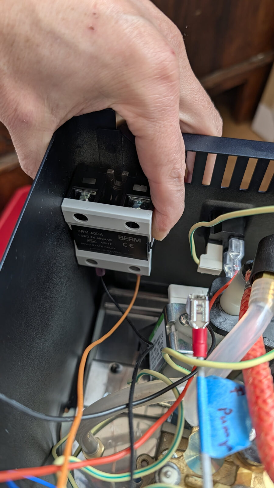
Full name: Solid State Relay — model DA40 (40-amp, 3–32V DC control signal, 24–480V AC output)
Replaces: The original mechanical relay inside the machine
Where it mounts: Bolted directly against the metal chassis — the metal acts as the heatsink
Critical: Must contact bare metal. No plastic spacers. No rubber feet.
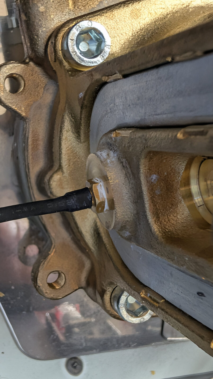
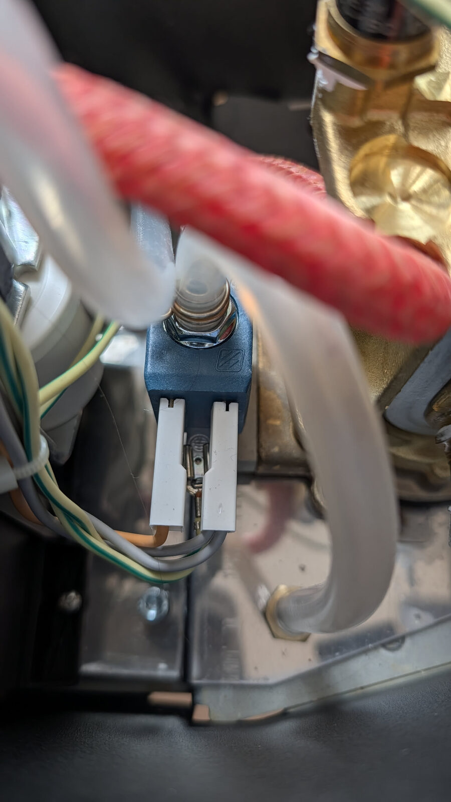
Thermocouple — the temperature sensor
Think of it as: A thermometer that screws into the boiler and reports the temperature 10 times per second.
The original machine used a bimetallic thermostat disc — a mechanical spring that physically bends when hot and cuts the circuit at a fixed temperature. It was imprecise (±5°C swing) and couldn't be adjusted.
The thermocouple produces a tiny voltage proportional to its temperature. The PCB reads this voltage 10 times per second and adjusts the boiler heater continuously. This is how the machine achieves ±0.5°C stability instead of ±5°C.
Full name: K-type thermocouple probe with M4 threaded tip
Replaces: The brew thermostat disc on top of the boiler
Installation: Finger-tight only — the probe tip is fragile; never use a spanner on it
Why it matters: No thermocouple = no temperature reading = no temperature control
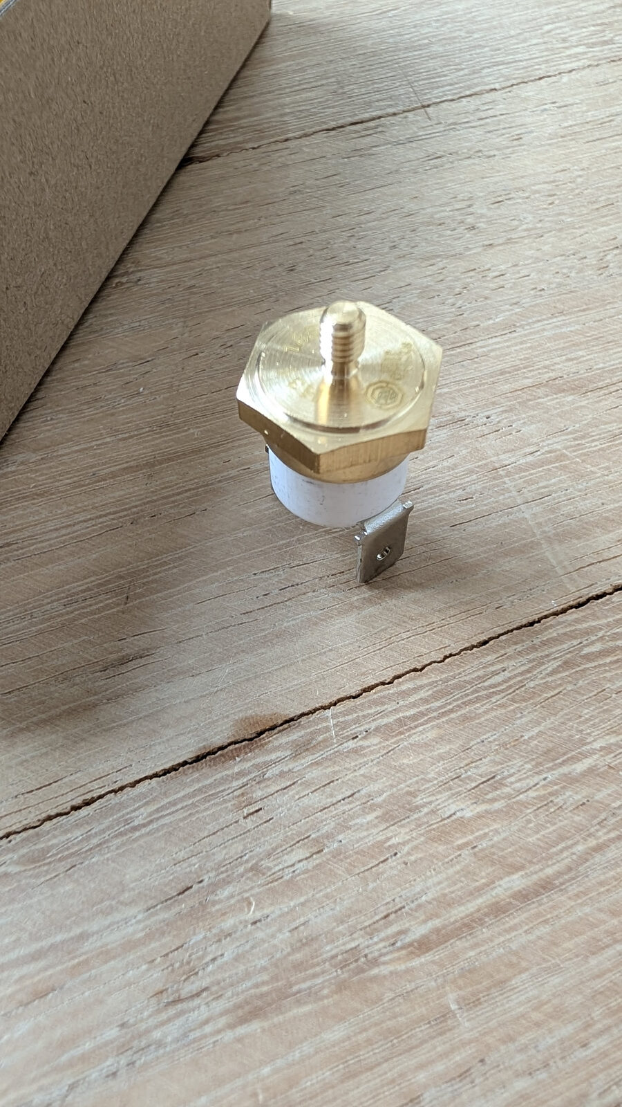
Brew Thermostat — the part it replaces
Think of it as: The original, imprecise temperature limiter — a bimetallic spring disc that physically bends to cut power at a fixed temperature. The thermocouple replaces it.
Full name: Bimetallic brew thermostat (disc type)
What happens to it: Removed from the boiler. The thermocouple probe goes in the same M4 hole. A jumper wire bridges the heater circuit at the thermostat's original spade terminals.
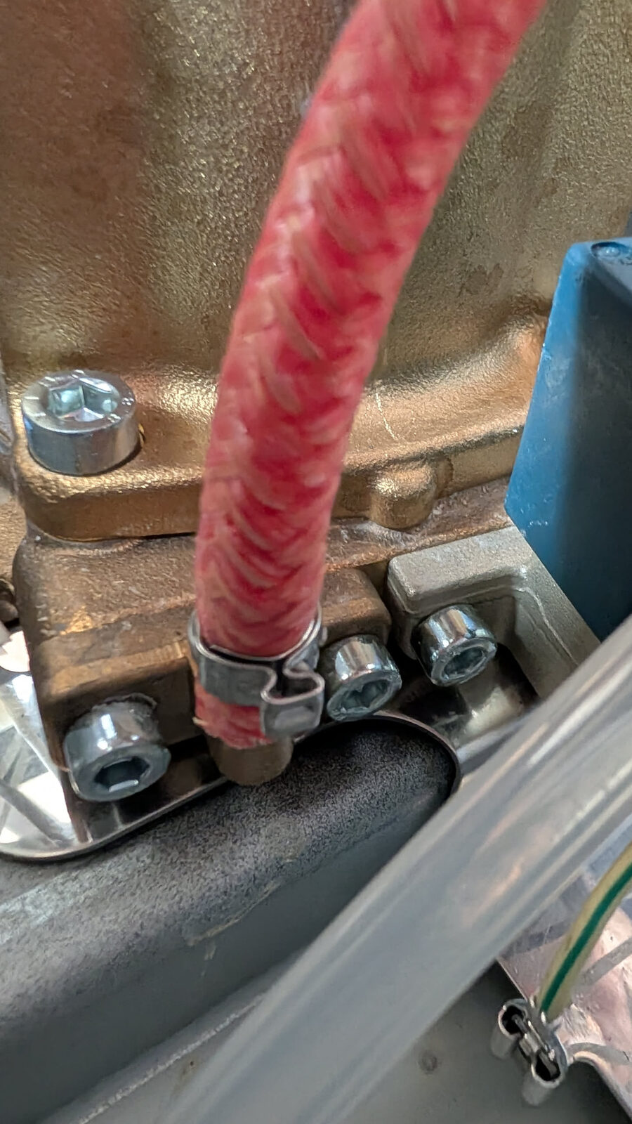
Thermal Fuse — the failsafe
Think of it as: A one-time safety fuse that permanently cuts power to the boiler heater if it ever overheats. If it triggers, something went wrong — find out what before replacing it.
The thermal fuse sits physically against the boiler body. If the thermocouple fails and the boiler overheats past the fuse's rated temperature, the fuse melts internally and permanently breaks the heater circuit.
Full name: Thermal cutout / thermal fuse
Where it mounts: Clamped against the boiler body — must make thermal contact with the metal
If it trips: The heater permanently stops. This is intentional. Investigate the root cause before replacing.
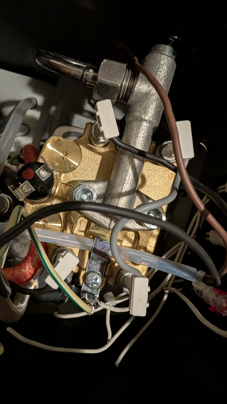
Pressure Sensor — the pressure reader
Think of it as: A sensor that measures how hard the water is being pushed through the machine — like a blood pressure cuff, but for your espresso.
The sensor converts water pressure into a voltage. The PCB reads this and displays it live on the HMI screen as a pressure curve during your shot. It is also how Gaggiuino knows when to dial pump power up or down for pressure profiling.
Full name: Pressure sensor, 0–1.2 MPa range, G1/4 straight thread, 3-wire (VCC / GND / Signal)
Where it mounts: Threaded into the PTB (Pressure Tube Block)
Thread type: G1/4 — straight (parallel) thread, seals with O-rings. Not NPT (tapered). Not interchangeable.
Critical: The 3-pin connector is keyed — do not force it in. Swapping VCC and Signal destroys the sensor.
PTB — the T-junction
Think of it as: A small stainless steel splitter that goes in the water line between the pump and the boiler, adding a third port where the pressure sensor can tap in.
Without the PTB, there is no way to connect a pressure sensor to the water path — the hose between pump and boiler is sealed. The PTB intercepts that hose and provides the measurement point.
Full name: Pressure Tube Block (CNC-machined food-grade stainless steel)
Where it goes: Inline in the pump outlet → boiler inlet water path
Connections: Hose clamp on inlet (pump side), hose clamp on outlet (boiler side), pressure sensor threaded into the third port
V4 PCB — the brain
Think of it as: The computer that runs the whole mod — reads every sensor, controls the pump and boiler, drives the display, and connects to Wi-Fi.
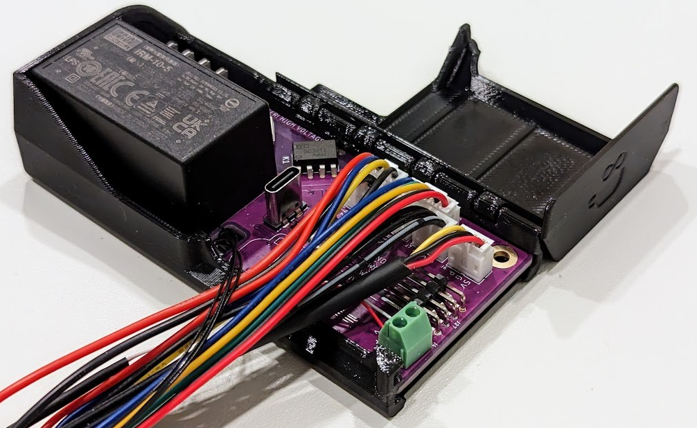 Image: Gaggiuino project — all rights reserved by contributors
The V4 PCB contains: - STM32U585 microcontroller — runs the Gaggiuino firmware, handles real-time sensor reading and hardware control - ESP32 — handles Wi-Fi, the web interface, and OTA firmware updates - USB-C port — for wired firmware flashing - Screw terminal block — connects the wiring harness (L, N, PE, pump, SSR, etc.) - Sensor connectors — thermocouple, pressure sensor, HMI, ToFnLED, scales
Full name: Gaggiuino GEN3 V4 Main PCB
Where it mounts: Inside the 3D-printed enclosure, positioned externally on the drip tray (recommended) or internally inside the machine
Comes: Pre-flashed from Peak Coffee — firmware already installed, no flashing needed unless you want to update
Eco PCB — what you remove
Think of it as: The original "smart" board that came with the E24 model. It is not needed for Gaggiuino and gets removed entirely.
The E24 model added an Eco PCB for the machine's auto-off feature. This board and its entire wiring harness are removed as part of the Gaggiuino installation. Everything it did is replaced by the V4 PCB with more precision.
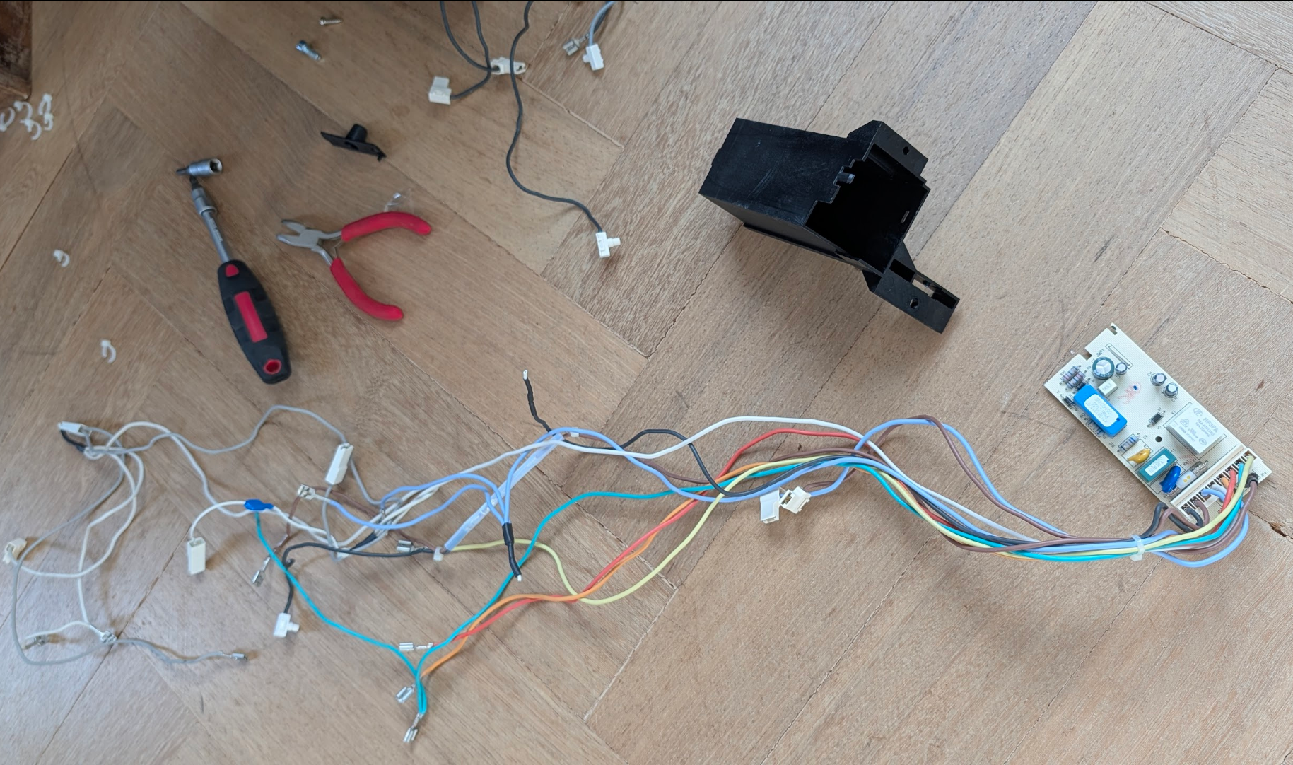
Full name: Eco PCB (E24 model's energy-saving control board + relay housing)
What happens to it: Fully removed — the PCB, the black plastic housing, and the entire wiring harness
What replaces it: The Gaggiuino V4 PCB
HMI — the touchscreen
Think of it as: The display and control panel for the whole mod — shows temperature, pressure, shot timer, and graphs. Also where you set profiles and configure settings.
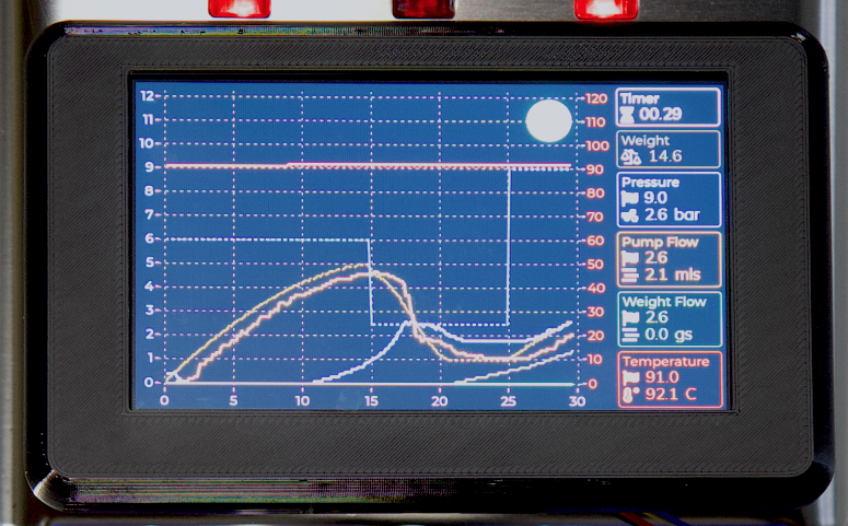 Image: Gaggiuino project — all rights reserved by contributors
Full name: 4.3" HMI touchscreen (Human-Machine Interface), pre-flashed with Gaggiuino UI
Where it mounts: On the front of the machine or on the side of the external drip-tray enclosure
Connection: Flat ribbon cable to the HMI connector on the V4 PCB
Three-Way Valve — the flow director
Think of it as: A valve that decides where the water goes — toward the coffee for brewing, or back to the reservoir to release pressure after the shot ends.
Without it, the group head stays pressurised after the shot stops, producing a wet, crumbling puck. The 3-way valve vents this pressure back to the reservoir automatically when the shot ends.
Full name: 3-way solenoid valve (3WV) — typically CEME or similar brand in GCP
Location: Bottom-centre of the machine interior, between the pump and the boiler/group head
Gaggiuino change: The V4 PCB controls the valve independently of the brew switch — enabling pre-infusion, controlled pressure release, and programmable shot sequences
ToFnLED — the water level sensor
Think of it as: A sensor that tells Gaggiuino how much water is in the tank — without touching the water — plus an LED ring for lighting.
ToF = Time of Flight. The sensor fires an invisible infrared pulse and measures how long it takes to bounce back off the water surface. Less water = longer return time = lower level reading.
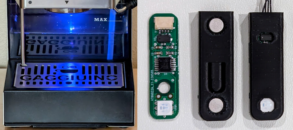 Image: Gaggiuino project — all rights reserved by contributors
Full name: ToFnLED module — VL53L0X Time-of-Flight sensor + RGB LED ring
Where it mounts: Inside the water tank cavity, facing upward toward the tank bottom
Connection: Flat ribbon cable to the V4 PCB
Wiring Harness — all the wires
Think of it as: A pre-made set of cables — every wire already the right length, the right colour, and with the right connector on each end. You connect them, not make them.
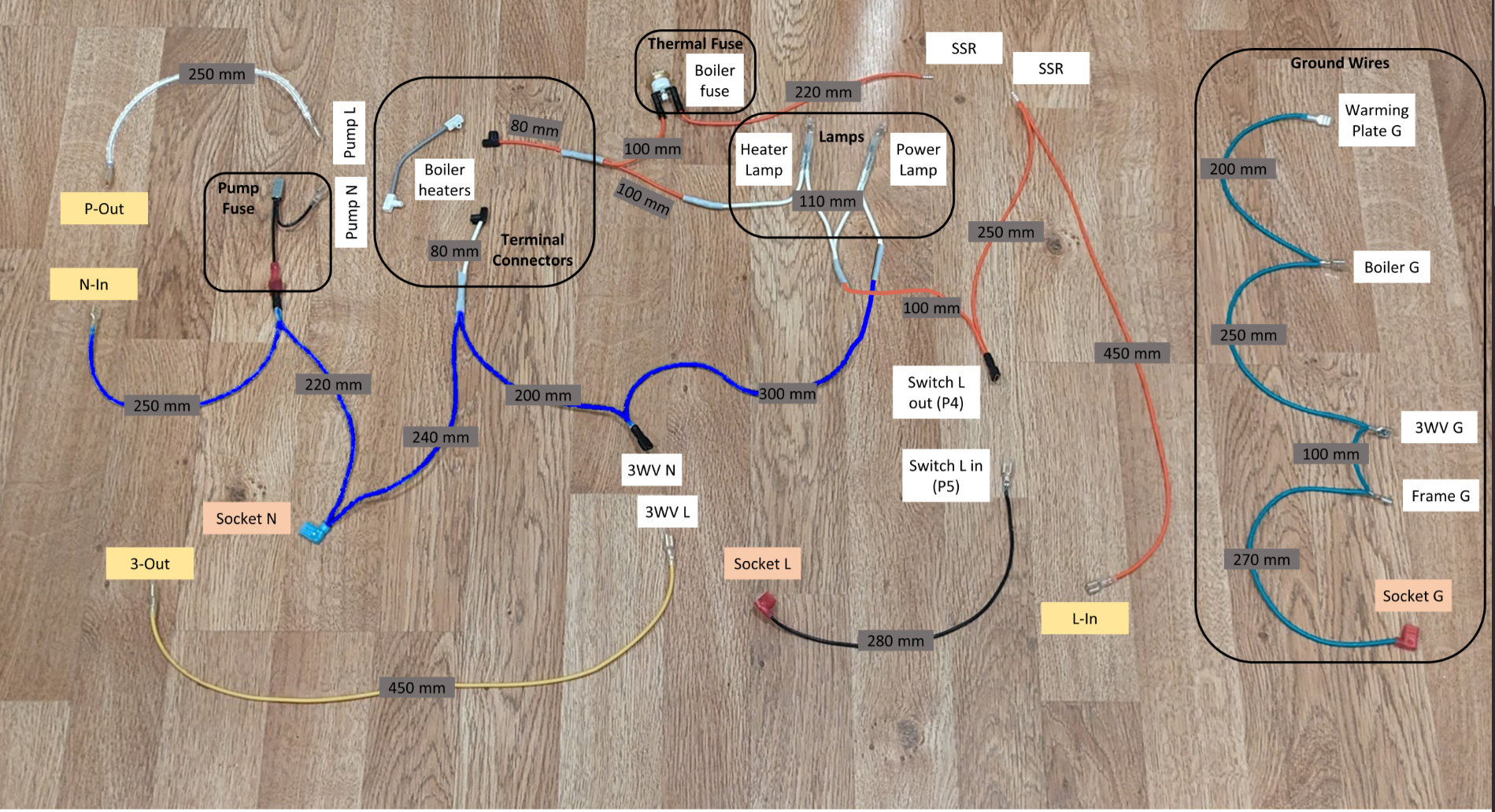
Contents: Pump group (× 2), boiler heater wires (× 2), 3-way valve wires (× 2), switch wires (× 2), lamp wires (× 2), mains socket wires (× 3), ground wire group (× 5)
Source: Pre-made in your Peak Coffee Complete Kit
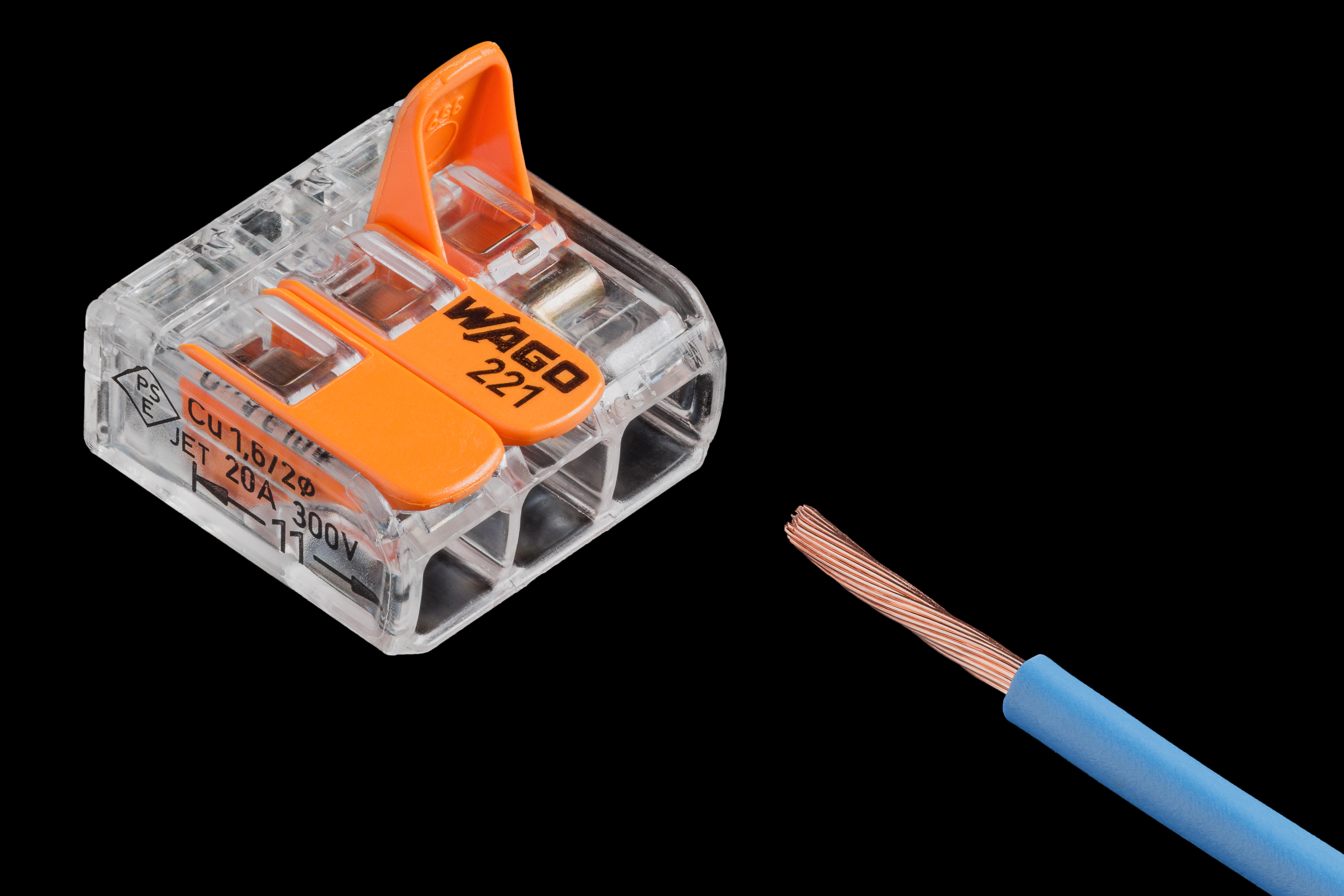
Wago Connector — the push-in junction
Think of it as: A push-in wire joiner — open the lever, push the wire in, close the lever. No crimping, no soldering. Used for the neutral (N) wire split.
 Lucasbosch / Wikimedia Commons / CC BY-SA 4.0
Full name: Wago 221 series lever-nut splicing connector
Used for: Neutral (N) wire junction — joins the original neutral wire and the harness neutral at the mains socket
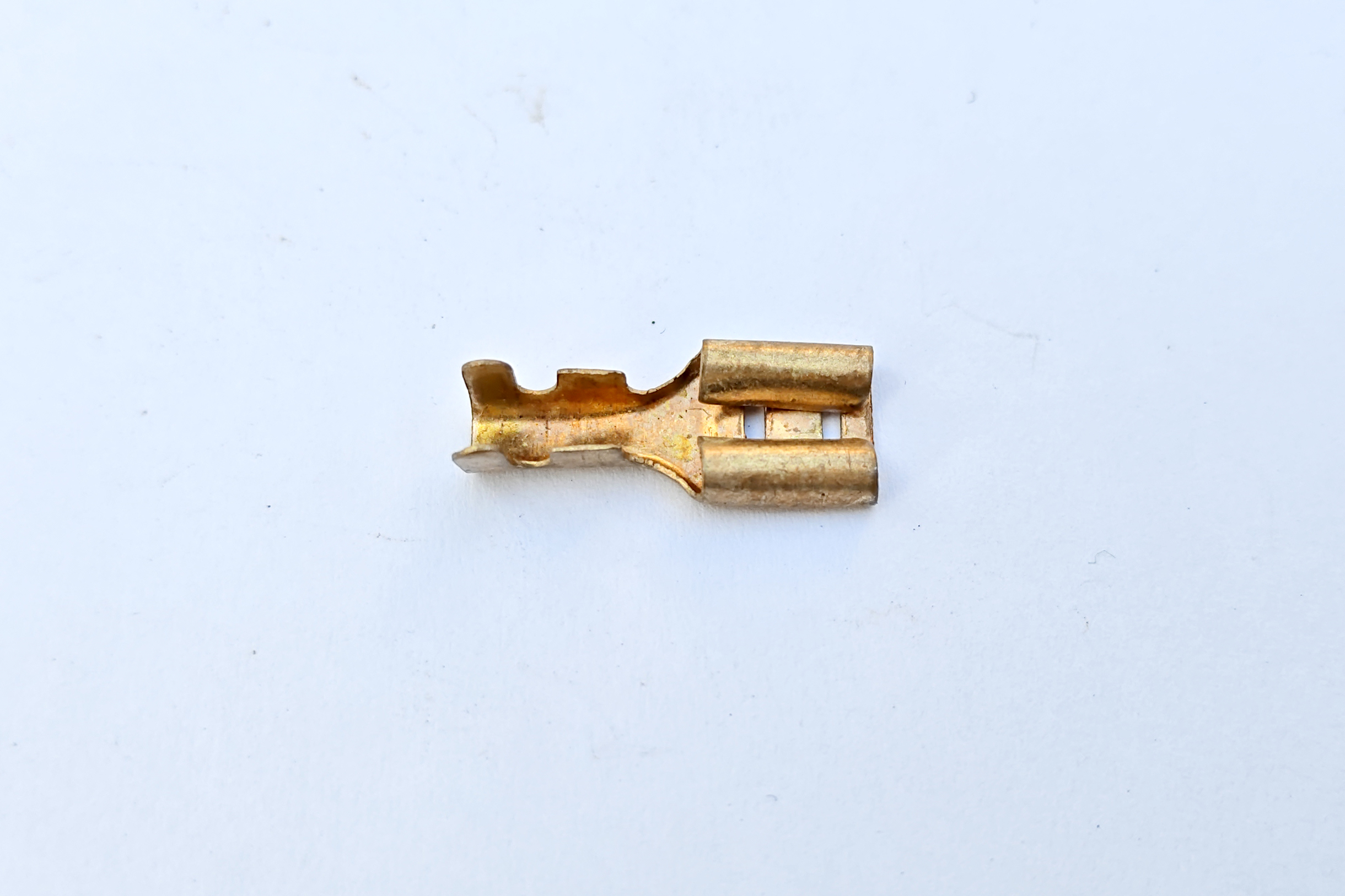
Faston / Spade Connector
Think of it as: A push-on electrical connector — a flat metal blade that slides onto a matching terminal. You crimp it onto the wire end. No soldering.
 Suyash Dwivedi / Wikimedia Commons / CC BY-SA 4.0
Sizes in this build: 6.3 mm (pump, valve, mains, switch) and 4.8 mm (lamp terminals)
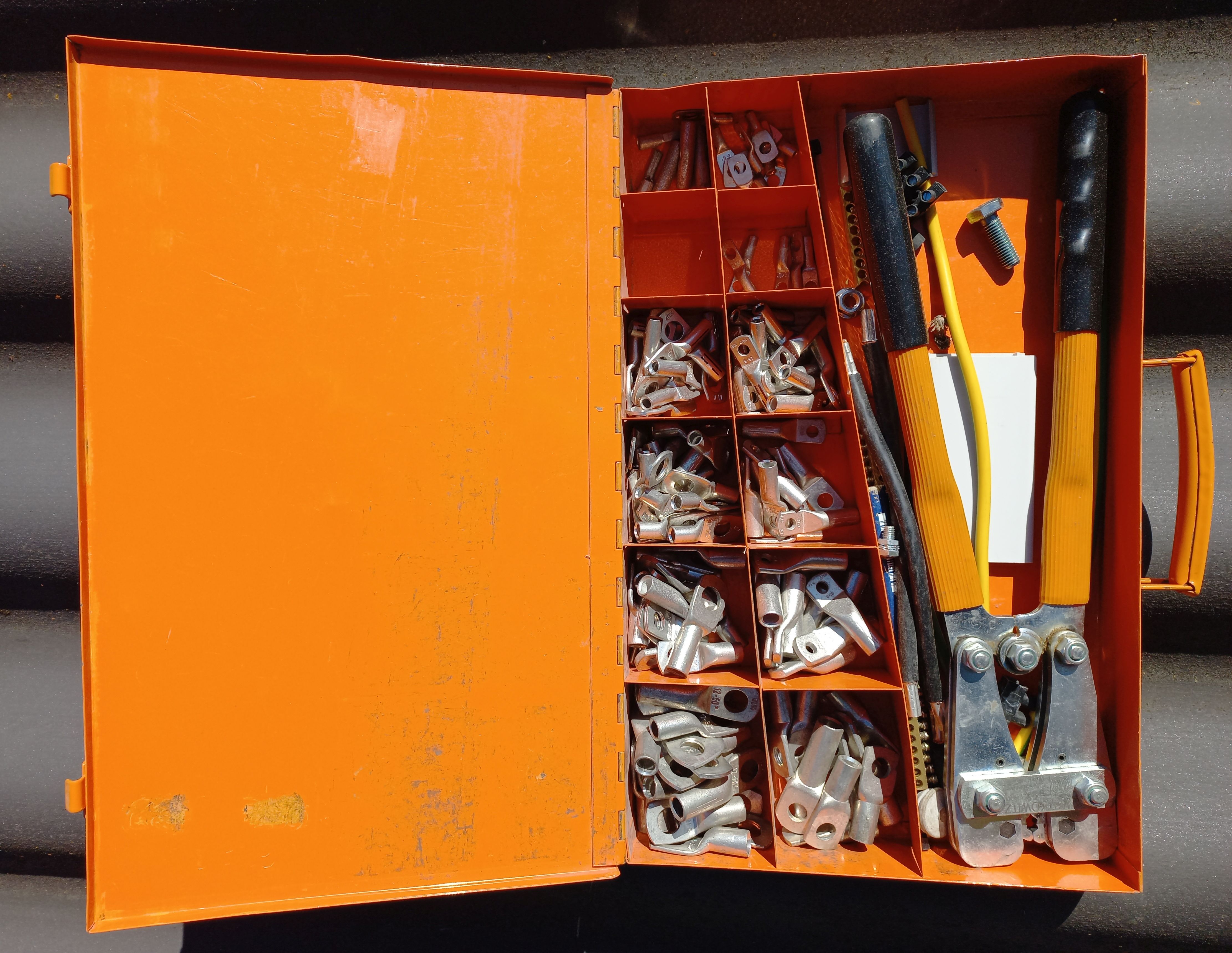
Crimping: Requires a ratchet crimping tool — see Chapter 1 BOM for the recommended BAURIX KAIRON SET
Ring Terminal — the earth eyelet
Think of it as: A circular eyelet that goes over a bolt. You crimp it onto the wire end, then the bolt clamps it to the metal chassis. Used for every ground (earth) connection in the machine.
 Asurnipal / Wikimedia Commons / CC BY-SA 4.0
Sizes in this build: M4 and M5 (the bolt diameter the eyelet fits over)
Used for: All 5 ground wire connections — warming plate, boiler, 3-way valve, frame chassis, mains socket earth
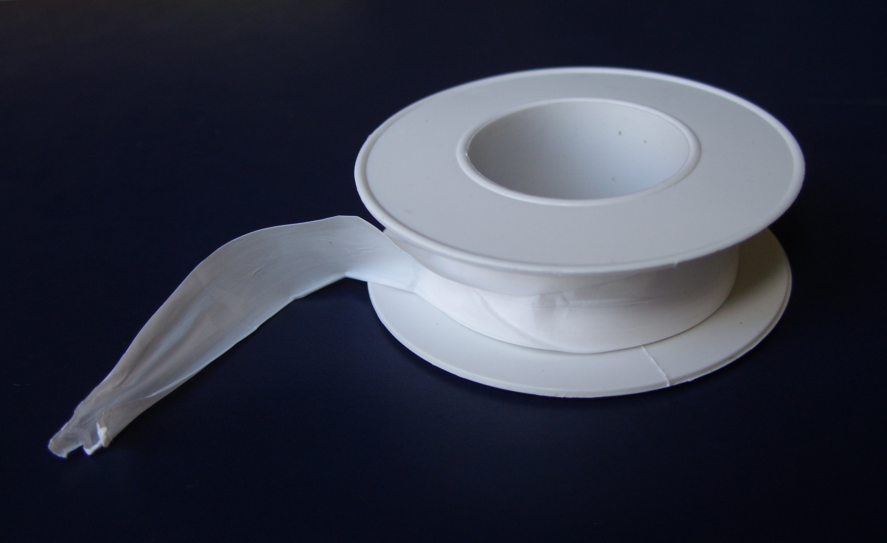
PTFE Tape — the thread sealant
Think of it as: White plumber's tape you wrap around a threaded fitting before screwing it in. Creates a watertight seal at the pressure sensor's thread.
 Bbarda / Wikimedia Commons / CC BY-SA 4.0
Full name: PTFE (polytetrafluoroethylene) thread seal tape — also called "plumber's tape"
Used for: Pressure sensor G1/4 thread before installation into the PTB
How to apply: 2–3 turns clockwise around the thread, starting from the tip. Stretch slightly as you wrap so it sits into the thread valleys.
Gaggiuino project images courtesy of gaggiuino.github.io — all rights reserved by contributors. Generic component photos from Wikimedia Commons under CC BY-SA 4.0.