Chapter 3 — Open the Machine
Chapter 3 of 10 · ~20 minutes · First time touching the machine
For this chapter, prepare:
- Phillips screwdriver PH2 (1×)
- The machine, unplugged from the wall — confirm this now
UNPLUG THE MACHINE
Physically remove the power cable from the wall socket. Not switched off — unplugged.
The mains voltage inside the Gaggia Classic Pro is present the moment the plug is in the socket, regardless of whether the power switch is on or off. Opening the machine while plugged in is dangerous.
STEP 1 — Empty and cool the machine
If the machine has been used recently, wait until it is fully cool to the touch. Open the steam valve briefly to release any residual steam pressure.
Remove the drip tray and empty it. Remove the water tank.
STEP 2 — Remove the top panel
The top panel is held by two Phillips screws at the rear of the machine. They are visible from the top, at the back edge of the panel.
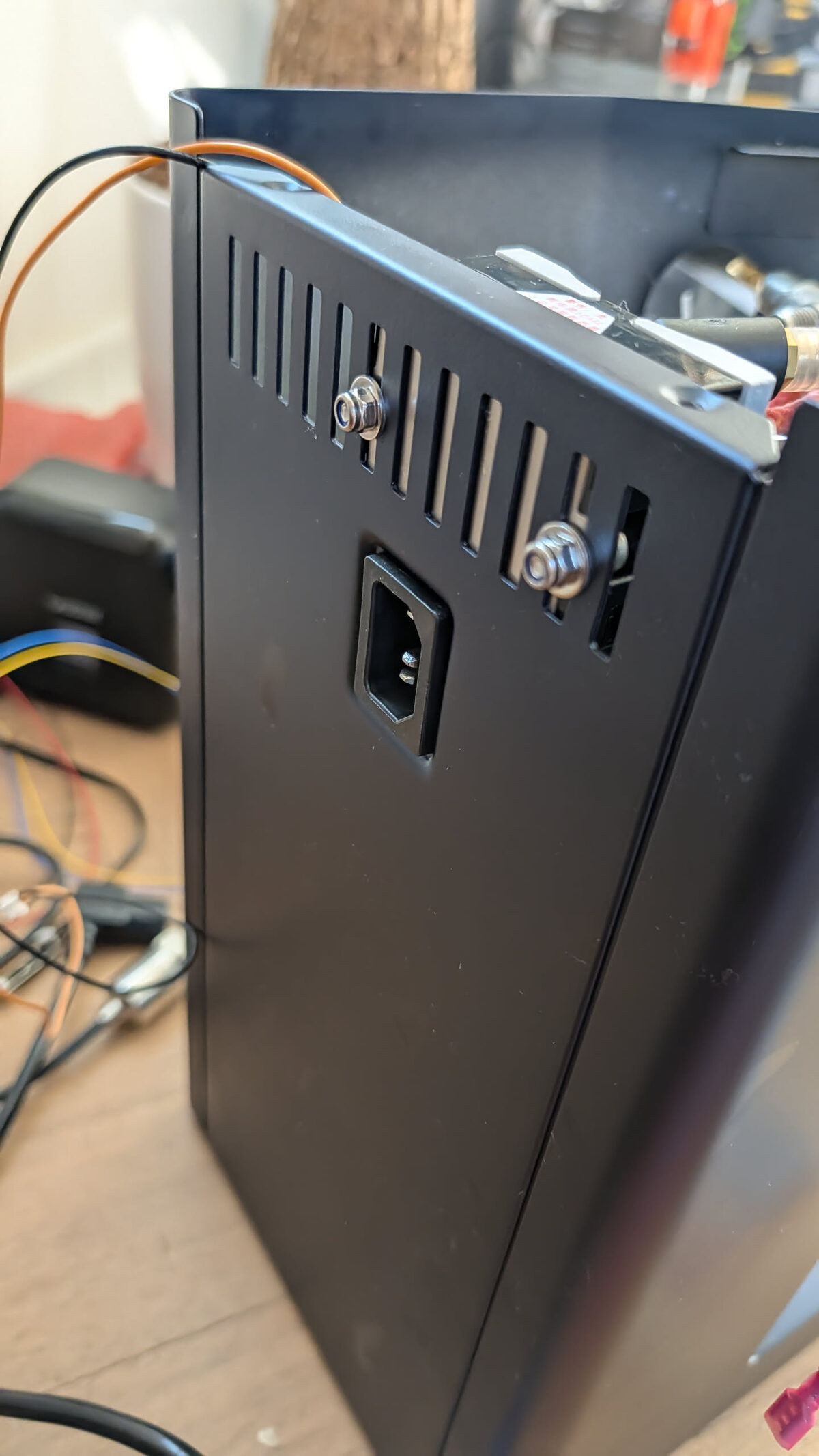
- Unscrew both rear screws and set them aside in a small cup — they are easy to lose.
- Slide the top panel backward approximately 2 cm. It sits in a channel and must slide before it can lift.
- Lift the top panel away and set it aside.
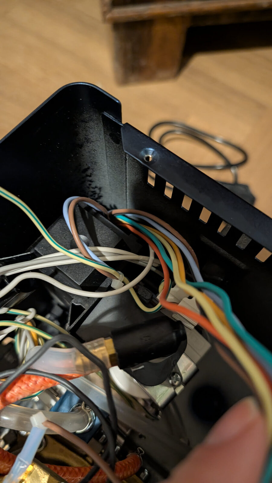
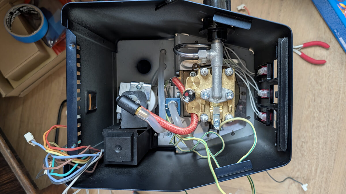
You should see: The top of the machine interior — the boiler (cylindrical metal component, the largest thing in the machine), the pump (black cylindrical motor at the left), and various wires and tubes.
STEP 3 — Orient yourself inside the machine
Take a moment to identify the main internal components before touching anything.
| What you see | What it is |
|---|---|
| Large metal cylinder | Boiler — heats the water |
| Black cylindrical motor (left side) | Vibration pump — pushes water |
| Black rectangular block | 3-way solenoid valve — routes water for brew/flush |
| Small green PCB (front area) | Eco PCB — the board we bypass in Chapter 4 |
| Disc on top of boiler | Brew thermostat — we replace this with the thermocouple |
| Wires everywhere | All original wiring — we do not cut any of this in stock integration |
Take a photo now
Before moving anything, photograph the interior with good lighting from directly above. This is your reference if you need to compare against original positioning later.
STEP 4 — Identify the Eco PCB
Find the small green PCB mounted near the front of the machine, close to the switches.
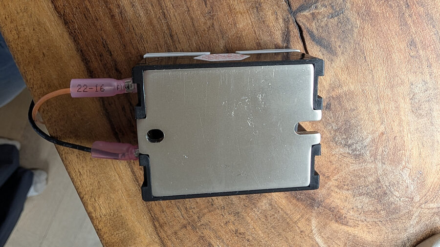
The Eco PCB is the component that requires modification in Chapter 4. It has: - A white multi-wire connector (the monoblock connector) on one side - Small surface-mount components on the board - Typically mounted with a single screw or adhesive standoffs
This confirms you have an E24 / Eco PCB machine.
STEP 5 — Identify the brew thermostat
The brew thermostat is a disc-shaped component on top of the boiler, held in place by a bolt or bracket.
This component gets replaced by the thermocouple probe in Chapter 7. For now, just locate it.
Checkpoint — Machine Open
Before moving on:
- Top panel is removed and set safely aside
- You have identified: boiler, pump, 3-way valve, Eco PCB, brew thermostat
- You have taken a reference photo of the original interior layout
- Machine is unplugged (confirm again)
Six screws and the top panel lifts off.