Build harness
Chapter 5 of 10 · Stage 3 of 4 · 3–5 hours · DIY builders only
← Back to: Stage 1–2 Overview
Switched from the kit bundle to custom?
You made the right call. The kit wires are unlabeled — you would have been reading the wiring diagram to identify every wire anyway. Custom gives you the right lengths for your routing and a harness you understand completely. Start here.
Time budget: 3–5 hours if you have never crimped before.
This is not a quick job. Do it in a dedicated session when you have a full evening and no interruptions. Done carefully on the first attempt, you will not need to redo it.
Your target state
Left: Pump group (Pump Fuse, Pump N, Pump L) + boiler heater terminals · Centre: 3WV N/L, Socket N/L, lamp wires, switch P4/P5 · Centre-top: [Thermal fuse](../../glossary.md#thermal-fuse) + boiler fuse + [SSR](../../glossary.md#ssr) wires · Right: Ground wire group — Warming Plate G, Boiler G, 3WV G, Frame G, Socket G (yellow)
Zoom in to verify connector types and wire lengths as you work. Source: Gaggiuino project (GPL-3.0).
Strategy: easy wires first
Crimping is a learned motion. The first few crimps will feel uncertain. By the time you finish the ground wires, the motion will be automatic. This is why you start with the simplest wires — not because they are the most important, but because they build the muscle memory you need before you touch the complex ones.
Work through this order — five rounds, simple to complex.
Round 1 — Ground wires (teal + yellow) — ring terminals
Start here. All five ground wires use the same ring terminal type on one or both ends. The wire is the same colour (teal or yellow). The only difference is length.
| Wire | Length | Terminals |
|---|---|---|
| 3WV G | 100 mm | Ring one end |
| Warming Plate G | 200 mm | Ring one end |
| Boiler G | 250 mm | Ring one end |
| Frame G | 270 mm | Ring one end |
| Socket G | 450 mm | Ring both ends (yellow wire) |
Cut five lengths, strip both ends. Crimp the ring terminal onto one end of each. You have five practice crimps before anything mission-critical.
Ratchet crimper technique
Insert the terminal barrel into the jaws (insulated sleeve away from the die). Insert the stripped wire until the copper fills the barrel. Close the ratchet fully until it releases — do not stop halfway. Tug the wire: it should not come out. If it pulls free, the crimp is bad — cut that end and redo it.
Round 2 — Single AC runs — spade connectors
Single-run wires with one connector on each end. Straightforward.
| Wire | Length | Connector A | Connector B |
|---|---|---|---|
| Heater Lamp | 100 mm | 4.8 mm spade | 4.8 mm spade |
| Power Lamp | 110 mm | 4.8 mm spade | 4.8 mm spade |
| 3WV N | 200 mm | 6.3 mm spade | 6.3 mm spade |
| 3WV L | 240 mm | 6.3 mm spade | 6.3 mm spade |
| Switch L out (P4) | 100 mm | 6.3 mm spade | PCB connector |
| Switch L in (P5) | 250 mm | 6.3 mm spade | PCB connector |
4.8 mm spades go on the lamp terminals. 6.3 mm spades go everywhere else in AC circuits.
Round 3 — Socket wires — mixed connectors
| Wire | Length | Notes |
|---|---|---|
| Socket L | 280 mm | Spade one end, red Faston other |
| Socket N | 200 mm | Spade one end, Wago other |
| Socket G | 450 mm | Already done in Round 1 |
The Wago on Socket N is not crimped — it is a push-in lever connector. Strip the wire end, open the Wago lever, push the wire in fully, close the lever.
Round 4 — Pump group — inline fuse
The pump group has an inline fuse in the Pump L wire. The fuse holder has two ends — both get crimped with spade connectors.
| Wire | Length | Notes |
|---|---|---|
| Pump N | 250 mm | 6.3 mm spades both ends |
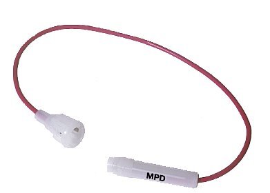
| Pump L | 220 mm total | Inline pump fuse — crimp wire into fuse holder ends |
The Pump L wire is actually two short wire segments joined by the fuse holder. Crimp the fuse holder ends first, then the outer spade connectors.
Round 5 — Boiler heater group — high-temp connectors
The two boiler heater wires (80 mm each) use uninsulated flat spade terminals rated for high temperature, covered with high-temp silicone tape or sleeve.
| Wire | Length | Notes |
|---|---|---|
| Boiler heater A | 80 mm | Uninsulated spade both ends |
| Boiler heater B | 80 mm | Uninsulated spade both ends |
Do not use standard insulated spades for the boiler heater connections
Standard plastic-insulated connectors will melt at boiler temperatures. Use uninsulated brass spades and cover immediately with high-temperature silicone tape (rated ≥ 200°C). Your kit includes the correct terminal type for this connection.
Consider angled (L-shaped) spades here
The boiler heater terminals sit in a tight corner. Straight uninsulated spades work but require pushing at an awkward angle. Uninsulated angled spades — same 6.3mm, same high-temp rating, same crimping technique — let you push the connector straight on without fighting the orientation. Look for "Flachstecker gewinkelt 6,3mm unisoliert" or "angled uninsulated Faston 6.3mm". Tape still goes on after crimping.
Final step — lay flat and photograph
Before routing the harness into the machine, lay everything flat on a table with all connectors spread out and photograph the full harness. This photo is your single most useful reference during Stage 4 installation. It shows connector types, wire colours, and lengths at a glance.
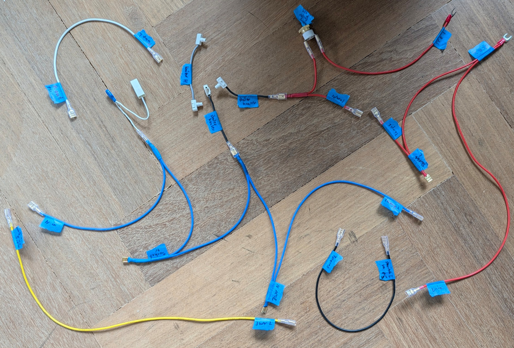
This is what a completed DIY harness looks like after a first build. Note the masking tape labels on every connector — this is exactly right. The labels come off before installation; they are your safety net during the build session.
The three paths Gaggiuino controls
Understanding these three paths is all you need to understand why the wiring looks the way it does:
Path 1 — Heater: Stock routes mains through the brew thermostat to the boiler heater. Gaggiuino routes it through the PCB → SSR. The PCB reads the thermocouple and pulses the SSR to hold ±0.5°C instead of ±5°C.
Path 2 — Pump: Stock routes mains directly to the pump. Gaggiuino routes it through the PCB's dimmer. The dimmer reduces pump power for pressure profiling.
Path 3 — Switch + 3-way valve: The PCB reads the brew switch state and independently controls the solenoid valve, decoupling shot start/stop from the mechanical switch action.
Wire colour reference
| Colour | Role |
|---|---|
| Blue | Neutral (N) |
| Orange / Red | Live (L) |
| Teal / Green | Ground (PE) — short runs |
| Yellow | Ground (PE) — long runs |
Harness built. That was the most manually intensive part of the build. Photograph the harness flat, then proceed to installation.