Chapter 7 — Electronics Mounting
Chapter 7 of 10 · ~45 minutes · Mounting and connecting all boards
For this chapter, prepare:
- V4 PCB (1×)
- SSR DA40 with safety cover (1×)
- Thermocouple probe (1×)
- ToFnLED module (1×)
- Scales PCB + load cells (2×) — Complete Kit only
- Phillips screwdriver PH2 (1×)
- M4 screws (2×) — for SSR mounting
- 3D-printed enclosure — ordered separately from Espressio (EU) or Hudson Creative Group (US)
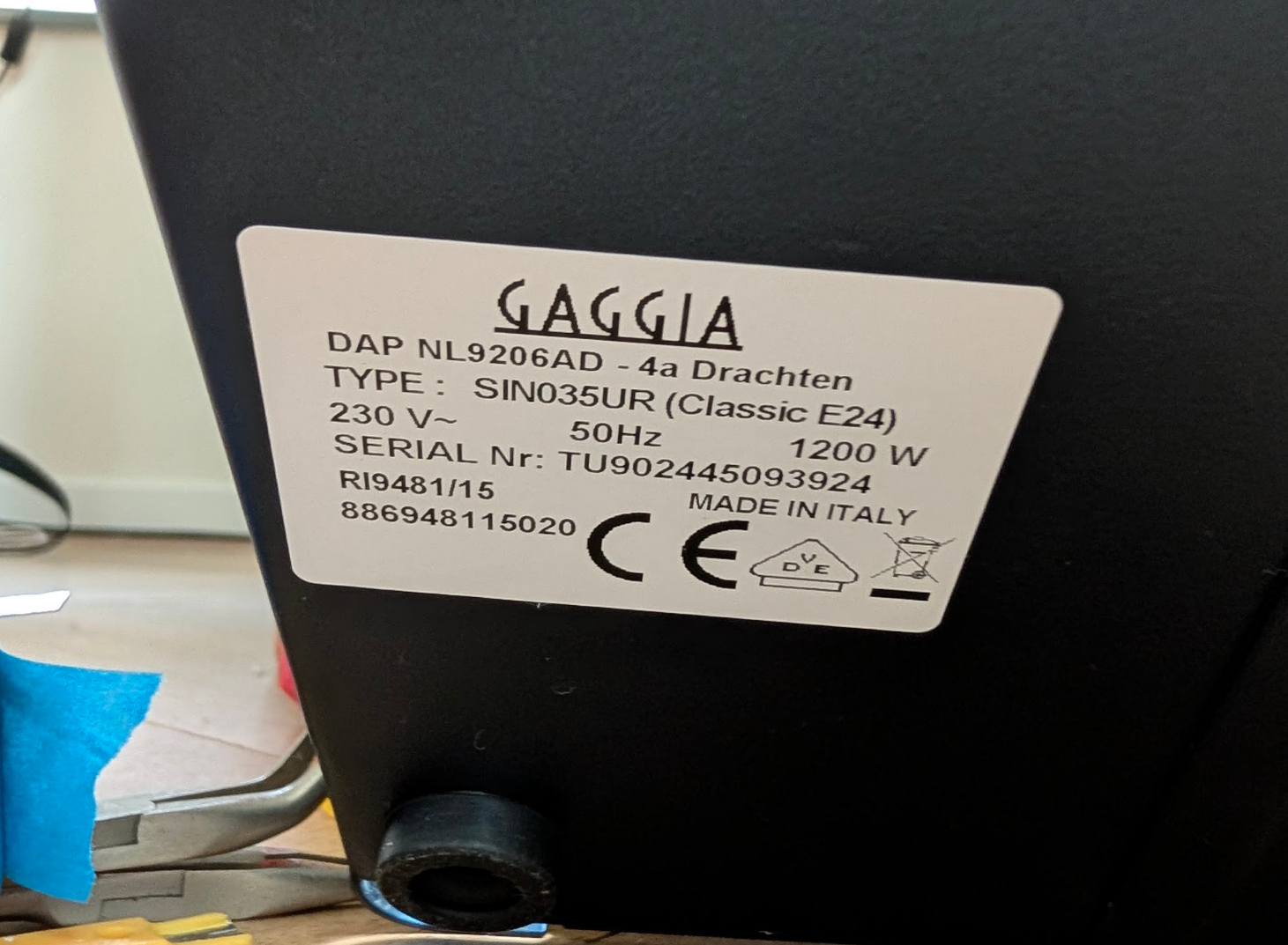
- The machine, unplugged
3D-printed enclosure — must be ordered before this step
The V4 PCB and HMI screen require a printed housing. This is not included in the Peak Coffee kit.
The community-standard housing is the GaggiaBoard PCBv3.1/v4 Housing by Loogle on Printables. It uses small neodymium magnets for tool-free removal — the PCB snaps in and out without screws. This is what most community members use. Print it yourself, or order from a local print service.
Commercial options: Espressio (EU) or Hudson Creative Group (US) also sell printed enclosures — allow 1–2 weeks delivery.
Internal mounting (inside the machine) and external mounting (on the drip tray) have different enclosure variants. External is recommended for first-time builders — easier to troubleshoot and swap.
STEP 1 — Mount the SSR
The SSR mounts directly to the machine chassis (the metal side panel or base) using the two M4 screws.
SSR MUST contact bare metal
The SSR uses the machine chassis as a heatsink. It must have direct metal-to-metal contact — no rubber feet, no plastic spacer.
An SSR running without a heatsink reaches dangerous temperatures within a few minutes of use.
- Choose a mounting location on the metal chassis — flat, accessible, away from water and vibration paths.
-
Apply a thin, even layer of thermal paste to the SSR's back face before mounting. A pea-sized amount spread across the surface is sufficient — the goal is to fill the microscopic air gaps between the SSR and the chassis, not to insulate with a thick layer.
Recommended: ARCTIC MX-4 (4g)
ARCTIC MX-4 — high-conductivity, non-electrically-conductive thermal compound. 4g is far more than needed for one build. Spec: 8.5 W/m·K conductivity, rated −40°C to +200°C.
Search: Arctic MX-4 thermal compound 4g — amazon.nl B07L9BDY3T
-
Mount with M4 screws. The SSR should be firmly against the metal surface.
The SSR has four terminals: - AC terminals (top, higher numbers) — connect to the boiler heater wires from your harness - DC terminals (bottom, 3–32V) — connect to the SSR control wires from the PCB
The PCB controls the SSR via the DC terminals; the SSR switches the boiler heater via the AC terminals.
STEP 2 — Install the thermocouple
The thermocouple replaces the brew thermostat disc on top of the boiler.
STEP 2a — Remove the brew thermostat
Remove the BREW THERMOSTAT only — the thermal fuse stays
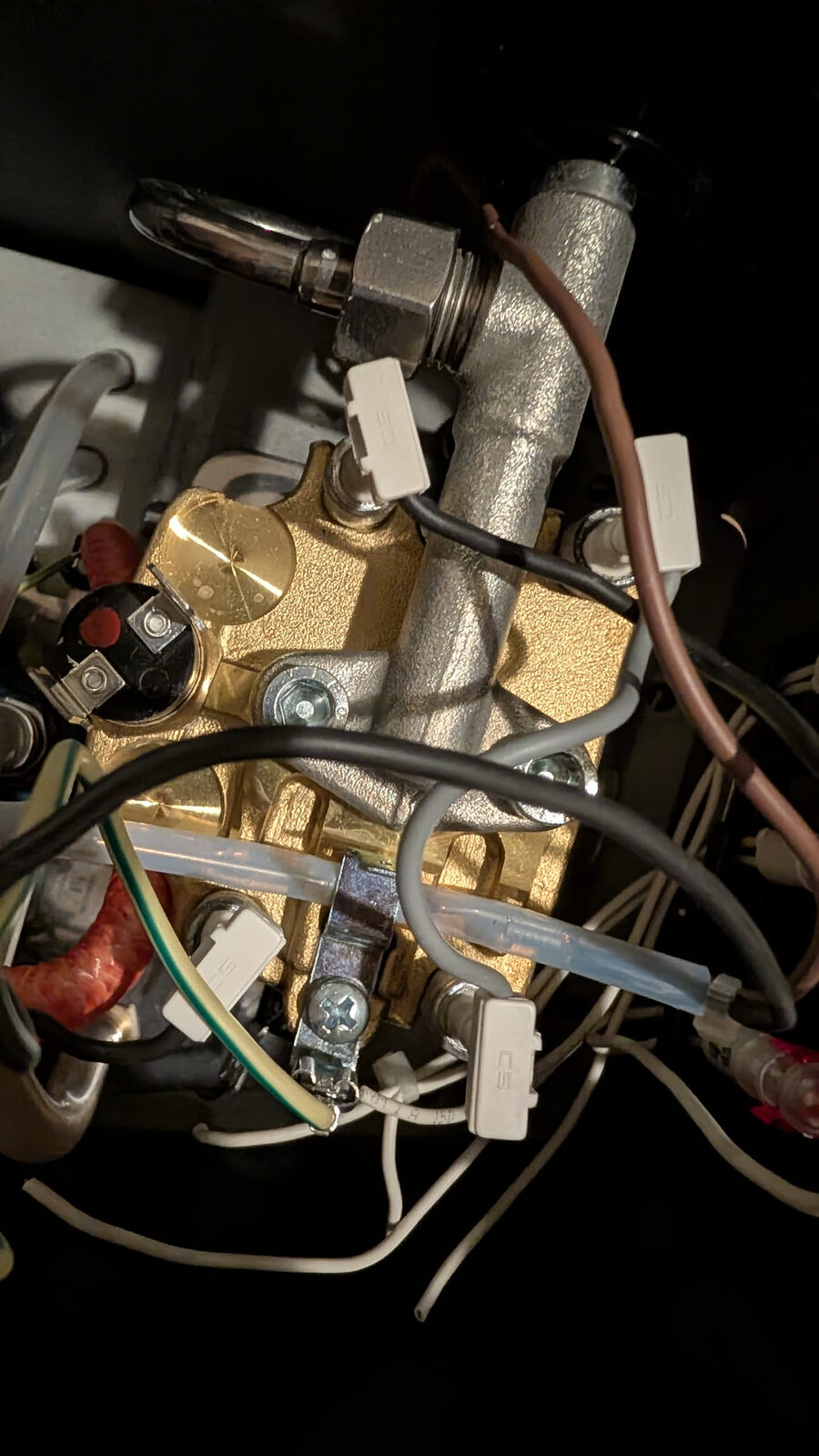
The boiler area has two temperature devices:
- Brew thermostat — the disc on top of the boiler. You remove this. The thermocouple goes in its place.
- Thermal fuse — the ceramic cylinder with wire leads clamped against the boiler body. Leave this exactly where it is. It is a one-time safety cutout. It stays for the life of the build.
Many builders mistakenly remove or disconnect the thermal fuse. Do not. A machine without a thermal fuse is a fire risk if the thermocouple fails.
- Locate the brew thermostat (the disc on top of the boiler, held by a bracket or centre bolt).
- Remove the two wires from the thermostat spade terminals.
- Undo the retaining bolt and remove the thermostat.
- Clean the thermostat mounting point on the boiler with isopropyl alcohol and a cotton swab. A clean surface ensures good thermal contact.
STEP 2b — Install the thermocouple jumper
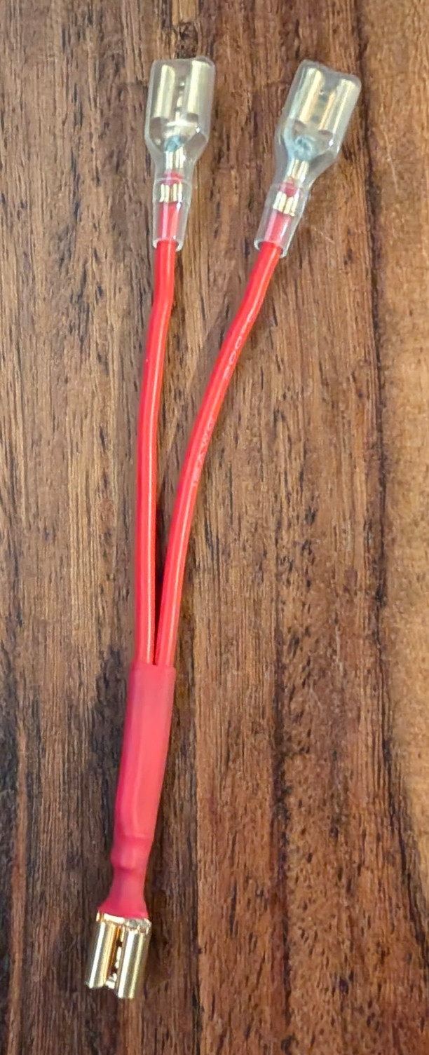
The thermostat created an electrical connection in the heater circuit. Removing it breaks that circuit. Install the jumper wire (included in the kit) to re-bridge the circuit at the thermostat mounting point.
The jumper is a Y-connector: one Faston female on the single end connects to the existing wire, and the two Faston females on the split end connect to the two original thermostat spade terminals. This re-closes the heater circuit without the thermostat.
STEP 2c — Install the thermocouple probe
- Thread the M4 thermocouple probe into the thermostat mounting hole on the boiler.
- Turn by hand until snug.
FINGER-TIGHT ONLY
The thermocouple probe screws into brass. Over-tightening damages the boiler thread or the probe tip.
Finger-tight means: turn until you feel resistance, then stop. Do not use a spanner on the probe itself.
- Route the thermocouple cable to the PCB connector labelled
THERMOCOUPLEorTC.
STEP 3 — Mount the PCB enclosure and PCB
Do not force the PCB into the housing
If the PCB does not seat into the enclosure without force, stop. Forcing it can snap surface-mount components off the board — particularly the small JST or USB port on the edge. This damage is permanent.
Check that you have the correct enclosure variant for the V4 PCB (not V3). Housing tolerances vary between suppliers and print services. If the PCB won't seat: widen the aperture slightly with a needle file, or order a replacement print. A broken enclosure is recoverable; a broken PCB is not.
- Mount the 3D-printed enclosure in your chosen location (external on drip tray, or internal in machine).
- Offer the V4 PCB to the enclosure before connecting any wires — confirm it seats fully without force.
- Connect the wiring harness connectors to the PCB screw terminals:
- Each terminal is labelled on the PCB silkscreen (L, N, PE, PUMP, SSR, etc.)
- Match the label to the wire from your harness
- Tighten screw terminals with a small flat-head screwdriver until snug
Screw terminal torque
Screw terminals should be tight enough that you cannot pull the wire out with moderate force. Hand-tight with a small screwdriver is approximately correct. Do not over-torque — you will strip the terminal.
J7 connector — Brew and Steam switch ground
The V4 PCB has a dedicated J7 JST connector for the ground lines of the Brew and Steam switches. A short cable connects J7 to the switch chassis ground terminal — it is separate from the main harness.
If you are using the kit bundle: look for a short cable with a JST plug on one end and two spade terminals on the other. It may be loose in the small parts bag. If you cannot find it, you can make one: a short length of wire, JST-XH2 pin on the PCB end, 4.8mm spade on the switch end.
Without J7 connected, the switch ground circuit is open — the machine powers on but the brew button does not register.
STEP 4 — Connect the HMI screen
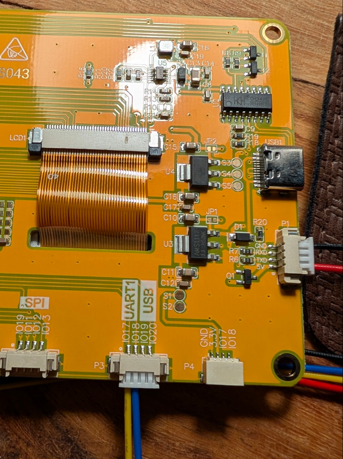
The back of the HMI board has several connectors. You use two of them:
- LCD1 (large flat ribbon connector, centre-left) — the display ribbon cable. Already connected from the factory.
- P1 (4-pin white connector, right side, labelled GND / RXD / TXD / 5V) — this is the UART connection to the V4 PCB. The yellow and blue wires in the photo connect here.
The labels IO17, IO18, IO19, IO20 visible on the board are GPIO expansion headers — not used in this installation. Ignore them.
- Route the HMI cable from the V4 PCB
HMIconnector to the screen's P1 connector. - Connect both ends — polarity matters. Match GND→GND, 5V→5V.
- The ribbon cable from LCD1 should already be connected on the back of the screen — do not disconnect it.
The ribbon cable connector has a locking latch. Ensure the cable is fully seated before closing the latch.
STEP 5 — Install the ToFnLED module (Complete Kit)
The ToFnLED module goes inside the water tank area. It measures water level via an optical Time-of-Flight sensor and provides LED illumination.
- Mount the module in the water tank cavity — it should face upward to measure the water depth.
- Connect the ToFnLED cable to the matching connector on the PCB.
- Route the cable so it does not interfere with tank removal.
STEP 6 — Install the scales (Complete Kit)
The scales go under the drip tray. This requires the external enclosure option.
- Mount the two load cells according to the scales PCB instructions included in the Complete Kit.
- Connect the load cell cables to the Dual Scale Board PCB.
- Connect the Dual Scale Board PCB to the V4 PCB via the provided cable.
Load cell wiring colour code: - Red — Excitation positive (E+) - Black — Excitation negative (E−) - White — Signal positive (A+) - Green — Signal negative (A−)
Load cell colour sequence is critical
Reversing any load cell wire pair produces incorrect readings or no readings. The colour sequence above is the standard. Verify before powering on.
STEP 7 — Final cable routing
Before closing up:
- Route all cables away from the pump (vibration degrades connectors over time)
- Route AC cables (orange and blue) away from DC signal cables (thermocouple, pressure sensor)
- Secure cables with small cable ties or velcro straps — tidy cable routing is functional, not just aesthetic
- Verify no cables are pinched or crossing moving parts
STEP 8 — Bench test before closing the machine
Do this before routing cables and closing the top panel. This is the moment to find any problem — while the machine is still open and accessible.
USB-C power only for this test — machine stays unplugged from the wall
You are powering the PCB only via USB-C (a phone charger or computer USB port). The machine mains cable must remain unplugged from the wall for the entire bench test.
Connect for the test:
- HMI screen connected to PCB (P1 cable and ribbon)
- Thermocouple connected to PCB thermocouple connector
- USB-C cable connected to PCB (power only — from a phone charger, not the machine)
Power on and verify:
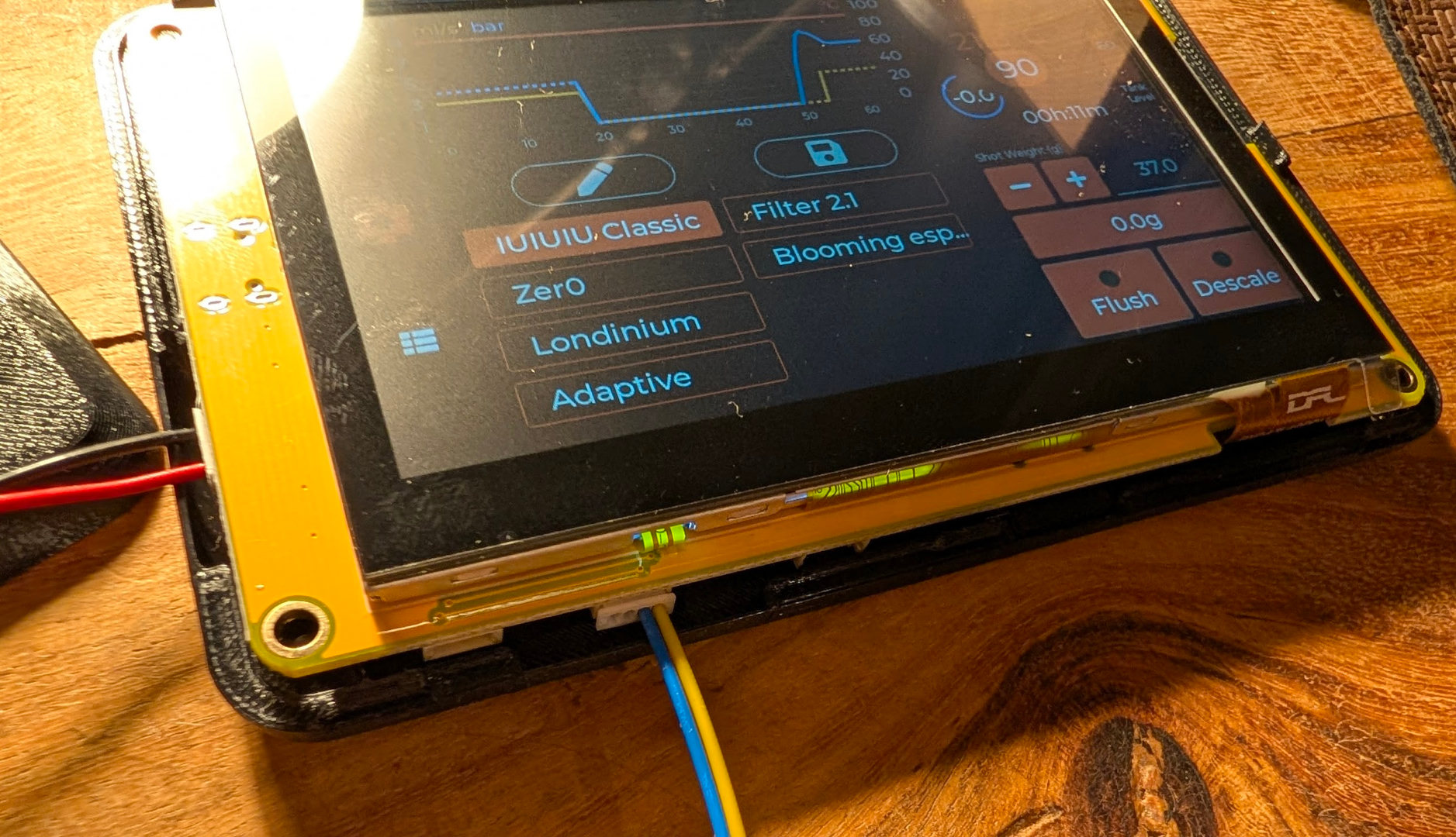
- Plug in the USB-C. The HMI screen should light up within 3 seconds and show the Gaggiuino boot sequence, then the profile selector.
- Check the temperature reading on the home screen. It should show approximately room temperature (18–25°C).
- Hold the thermocouple probe tip between your fingers for 30 seconds. The temperature reading should rise toward body temperature (~37°C). This confirms the thermocouple is reading and not reversed.
- If the screen is blank: recheck the HMI P1 connector — both ends. Verify the ribbon cable latch is fully closed.
- If temperature reads -200°C or a fixed wrong value: recheck the thermocouple connector at the PCB. If reversed, unplug and re-insert with opposite orientation.
Pass: Screen boots, temperature reads room temp and rises when probe is held.
Fail: Stop. Fix before closing. Much easier now than after reassembly.
Disconnect USB-C when done. The machine stays unplugged.
Checkpoint
- SSR mounted to bare metal chassis, firmly secured
- Thermocouple installed finger-tight in boiler
- PCB seated in enclosure, all harness connectors tightened
- HMI screen connected, ribbon cable fully seated
- ToFnLED connected (if Complete Kit)
- Scales installed and connected (if Complete Kit)
- Cables routed away from pump and heat sources
- Bench test passed: screen boots, thermocouple reads room temperature
You're 75% done. Physical build verified. Firmware next, then first power-on from mains.
Next: Chapter 8 — Firmware