Overview
Chapter 5 of 10 · Simpler than it looks · Four stages
The number of connections is finite. They come one at a time. Following the overview diagram is genuinely enough to get every wire right — no prior electrical experience needed.
Start with the shorter, simpler wires and work toward the more complex ones. The rhythm builds fast. By the time you reach the boiler and switch connections, the motion is automatic. It is more satisfying than it looks from the outside.
The wiring diagram
This is the reference you will use throughout all four stages. Open it on your phone before Stage 2 and keep it there.
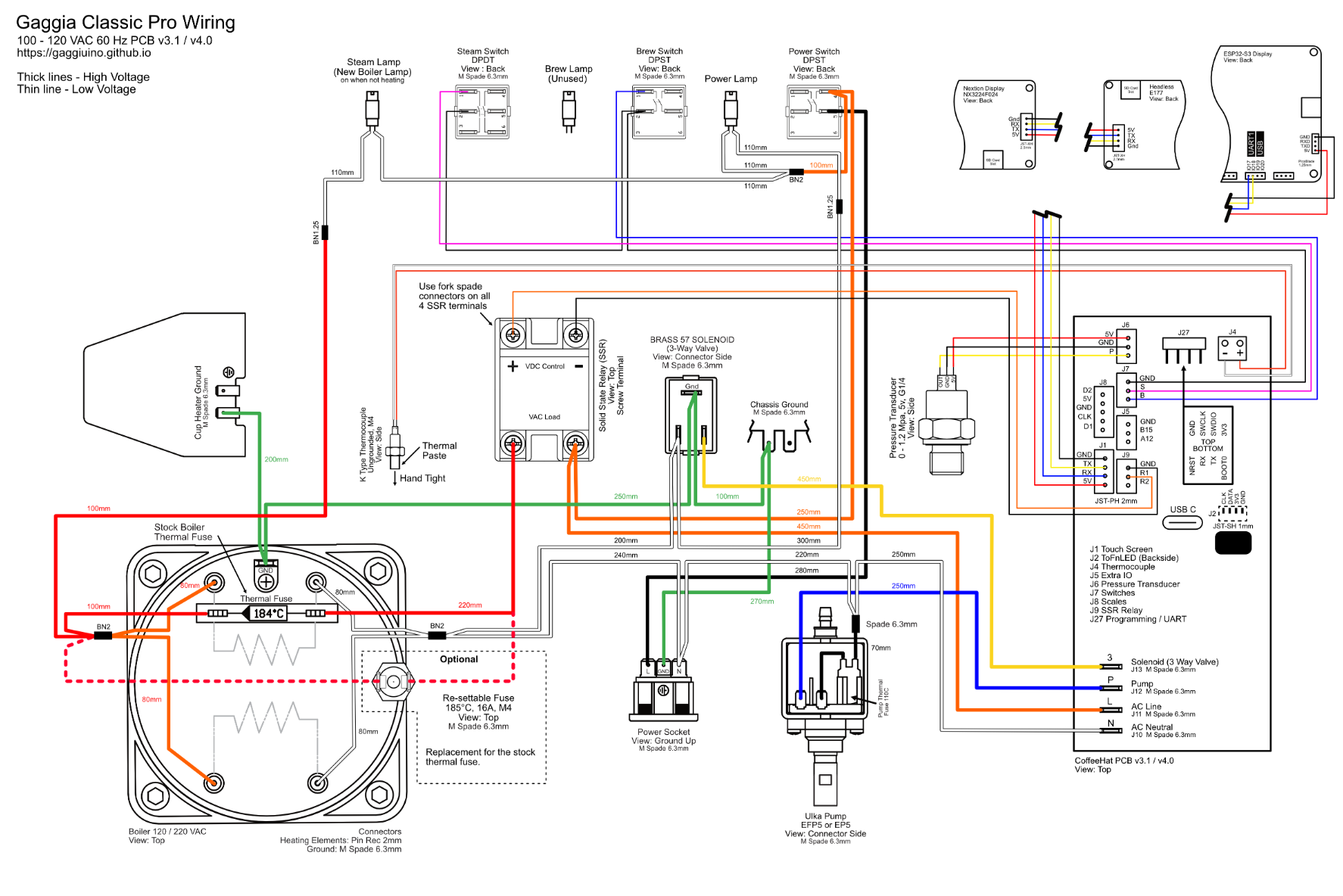
Every terminal is labelled. Every wire colour matches the harness you will build in Stage 3. Zoom in freely — it is high resolution.
Stage overview
| Stage | What you do | Machine state |
|---|---|---|
| 1 — Stock | Open the machine, orient yourself | All original wiring intact |
| 2 — Gutted | Disconnect the right wires, leave the rest | Specific wires removed, original harness mostly intact |
| 3 — Harness ready | Build or verify the new harness | Machine open, harness laid out and photographed |
| 4 — New wiring in place | Install all new connections | Gaggiuino harness connected, machine ready to close |
Machine unplugged for all four stages
All wiring work happens with the machine physically disconnected from the wall. Unplug before opening. Verify by trying the switch — nothing should happen.
Stage 1 — Stock
When you first open the Gaggia Classic Pro E24, this is what you are looking at.
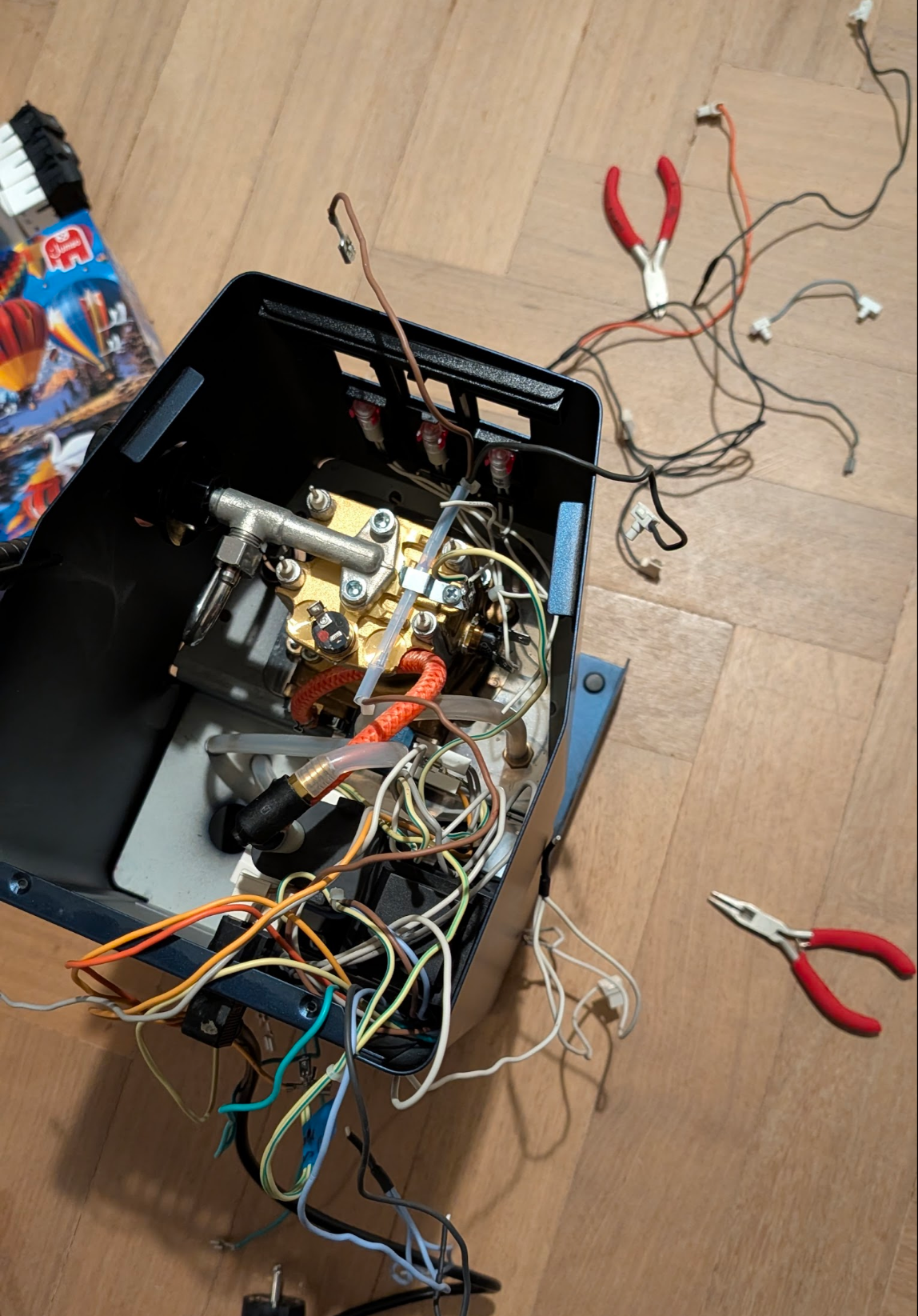
Yes, it looks like that. This is normal. You are not the first person to open this machine and think "what am I looking at."
The interior has four main components connected by wiring:
- Pump — black cylindrical motor, upper-left. Two wires: Live (orange/brown) and Neutral (blue).
- Boiler — large brass/aluminium block, centre-right. Two heater terminals on the base; the brew thermostat disc and thermal fuse on the side.
- 3-way solenoid valve — bottom centre, two wires.
- Brew switch — front panel, multiple terminals (more than you expect on the E24).
- Mains socket — back of the machine, three wires: L, N, Earth.
- Eco PCB — small circuit board in its black plastic housing, left side. E24-specific. You will remove this entirely.
Photograph everything before touching anything
Take one wide-angle photo of the full interior and individual close-up photos of: - The pump terminals - The boiler heater terminals - The brew switch terminals - The mains socket terminals
These photos are your reference if anything gets confusing later.
Stage 2 — Gutted
This stage is simpler than it looks. You are removing the Eco PCB and its harness entirely, then disconnecting specific wires at their terminals. You are not cutting anything. Every connector pulls off by hand or with needle-nose pliers.
What you remove completely
The Eco PCB assembly — the black plastic housing on the left side contains the Eco PCB circuit board and its full wiring harness. This entire assembly comes out. Unplug every connector from the machine, unscrew the housing, and set it aside.
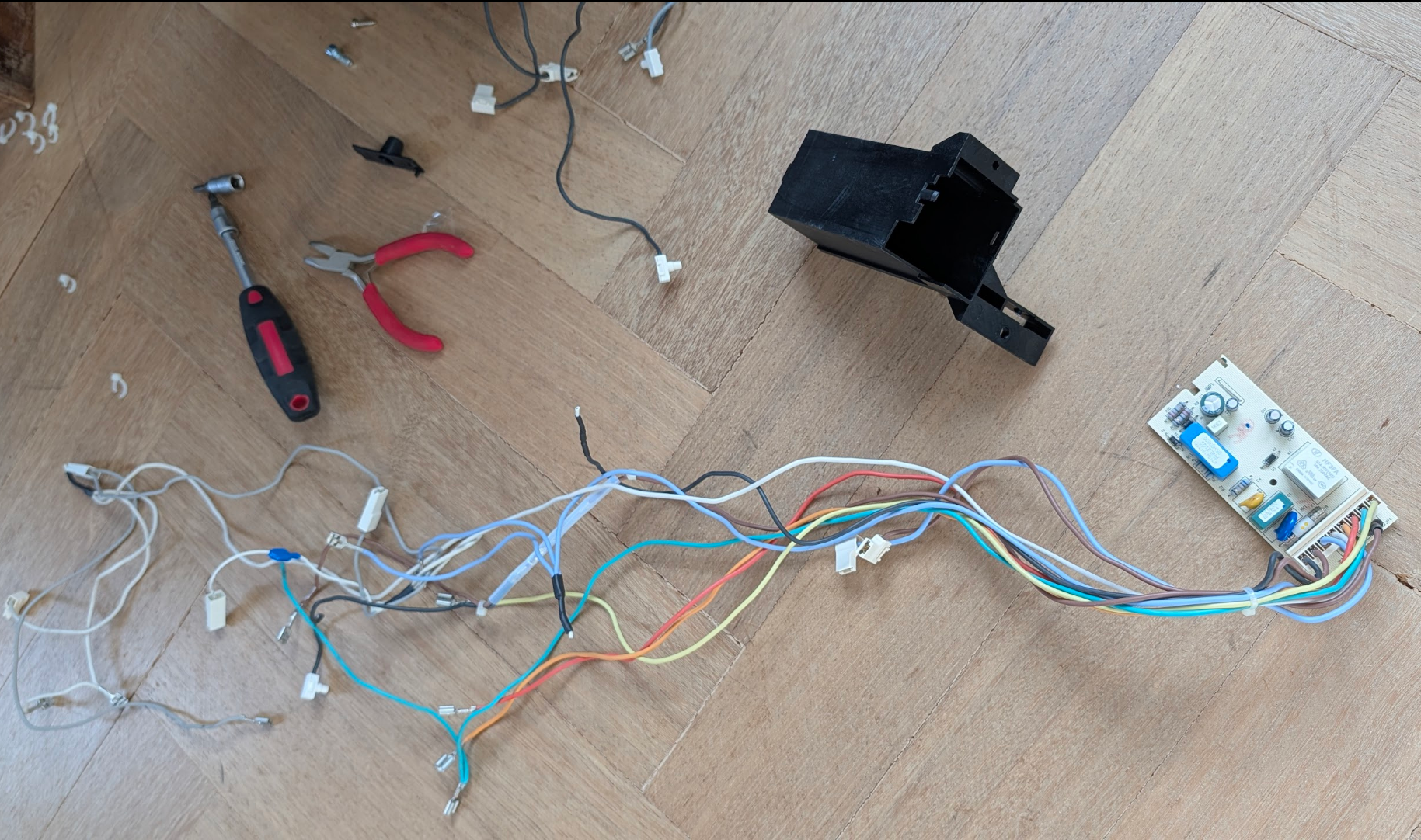
This is what you removed. The entire Eco PCB harness — every white connector, the board, the housing. It goes in a box or bag and is not reinstalled.
What you disconnect at the terminals
| Location | What | Why |
|---|---|---|
| Mains socket | The 3 original socket wires (L, N, Earth) | Gaggiuino harness socket wires connect here instead |
| Pump | Both original pump wires | Gaggiuino harness pump wires connect here instead |
| Boiler heater terminals | The 2 heater wires | Gaggiuino harness boiler wires connect here instead |
| Brew thermostat | The 2 wires on the disc | Thermocouple and jumper go here instead |
| 3-way valve | Both wires | Gaggiuino harness 3WV wires connect here instead |
| Brew switch | The Live wires at the switch | P4/P5 switch wires re-route through PCB |
Before disconnecting: open the wiring diagram on your phone
Use the full diagram at the top of this chapter — it shows every terminal on every component. Zoom into the switch, socket, and boiler sections before you pull any connector.
The front lamp wires — one cut required
The two front indicator lamp wires (from the power and heater lamps on the front panel) run into the Eco PCB harness via long wire runs. When you remove the Eco PCB harness, these wires come with it — but they need to stay in the machine for the Gaggiuino harness to connect to.
Trim the lamp wires back to the heat shrink — cut just above the heat-shrink sleeve near each lamp, leaving the short stub with the spade connector still attached to the lamp. The Gaggiuino harness lamp wires connect to these stubs.
What you leave completely untouched
- The warming plate ground wire
- The frame ground structure
- The mains socket housing (only the wires are disconnected, not the socket itself)
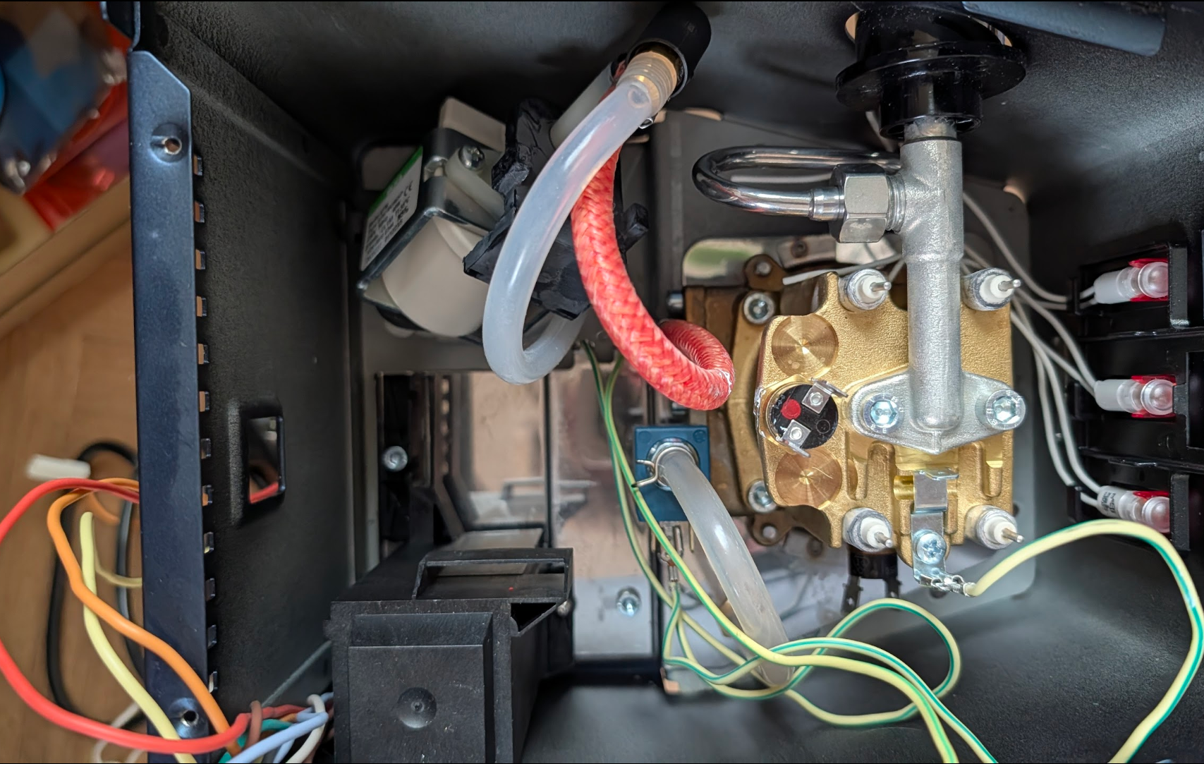
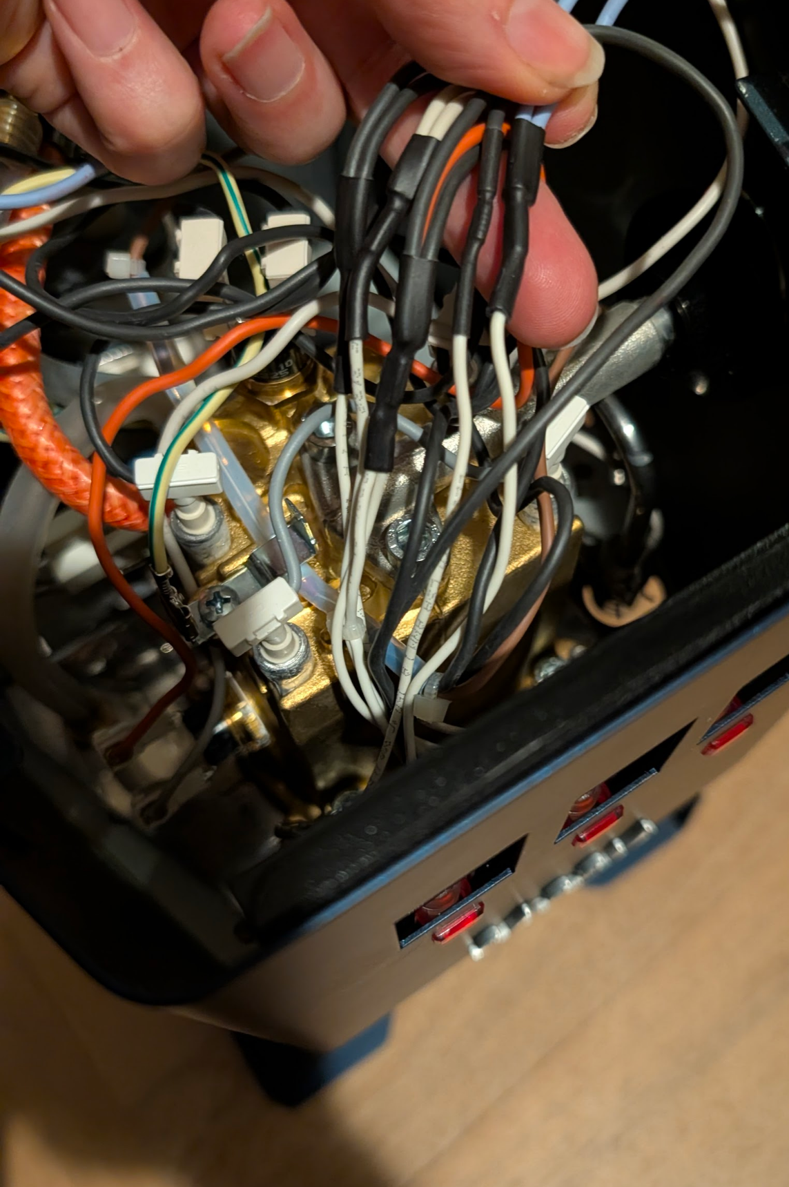
This is the moment that scared you in every build thread
Every mid-wiring photo you saw online looked chaotic. The chaos is just disconnected ends hanging loose. The original components — boiler, pump, 3-way valve — stay in place. Several connectors hang free from their terminals. That is correct. Once the Gaggiuino harness is connected and routed, it looks clean. The actual work in Stage 4 is straightforward: one connector at a time.
One thing to do differently next time: angled spades at three spots
Three places on the machine have terminals in tight, recessed spaces — the boiler heater, the brew switch, and the mains socket. Standard straight Faston spades work in all three, but you have to push them home at an awkward angle with limited clearance. Angled (L-shaped) Faston spades solve this: the wire runs perpendicular to the push-on direction, so you connect cleanly without twisting your wrist into the machine.
For the boiler heater terminals: use uninsulated angled spades rated ≥200°C — the high-temp requirement still applies, the angle is just a shape difference. For the switch and socket: regular insulated angled Fastons work (4.8mm for switch lamp terminals, 6.3mm for socket and switch signal wires). Search for "angled Faston 6.3mm" or "Flachstecker gewinkelt 6,3mm".
Stage 3 — Harness ready
Have ready for this stage:
- Wiring harness (see below — kit or custom)
- Thermal fuse (from your kit)
- Jumper wire / Y-connector (from your kit)
- Multimeter
- Needle-nose pliers
- Masking tape + pen
Kit harness or custom wiring — which should you use?
If you have a Peak Coffee kit harness — read this before touching anything
The Peak Coffee harness bundle does not match the official Gaggiuino wiring diagram. The wiring is assembled differently — non-standard routing, different wire groupings, different lengths — and there is no separate documentation that maps the kit wires to the diagram.
The wires are also unlabeled. They arrive in small bags with no tags and no markings. The official diagram you have open on your other screen will not reliably tell you which wire in the bag does what.
This combination — non-standard + unlabeled + no documentation — is what traps builders. You cannot install what you cannot identify. If you are in this position, your best immediate step is to post your harness photo in the Gaggiuino Discord #help-gcp channel; someone with the same kit may be able to identify the wires from the photo.
The honest recommendation: if you have not yet committed to the kit harness, build custom.
Buy 3m each of the wire colours from the official diagram, a pack of Faston spade terminals (4.8mm and 6.3mm), ring terminals, and Wago 221 connectors. Total cost is under €15. Delivery from any electrical supplier is days, not months. The result is a harness that matches the diagram exactly, that you can trace and verify every connection on, and that you built so you understand completely.
Custom wiring is not harder than the kit — it is the same work, with documentation that actually matches what you are building.
The lesson: the diagram is the real harness; the physical wires are just its execution.
Proceed to: Stage 4 — New Wiring In Place