Chapter 6 — Pressure Transducer
Chapter 6 of 10 · ~30 minutes · Water path work
For this chapter, prepare:
- PTB (Pressure Tube Block) (1×)
- Pressure sensor with 2 O-rings (1×)
- Pressure hose (25cm) (1×)
- Hose clamps (4×)
- Adjustable spanner or 22mm wrench (1×)
- PTFE tape (1×) — thread sealant
- The machine, unplugged
Machine unplugged
Confirm unplugged before starting.
What the PTB does
The pressure sensor measures the water pressure inside the machine so Gaggiuino can display and control it. To measure this, the sensor needs to tap into the water line between the pump and the boiler.
The Pressure Tube Block (PTB) is a T-junction: water enters from the pump, exits toward the boiler, and the third port connects to the pressure sensor. It is made from food-grade stainless steel.
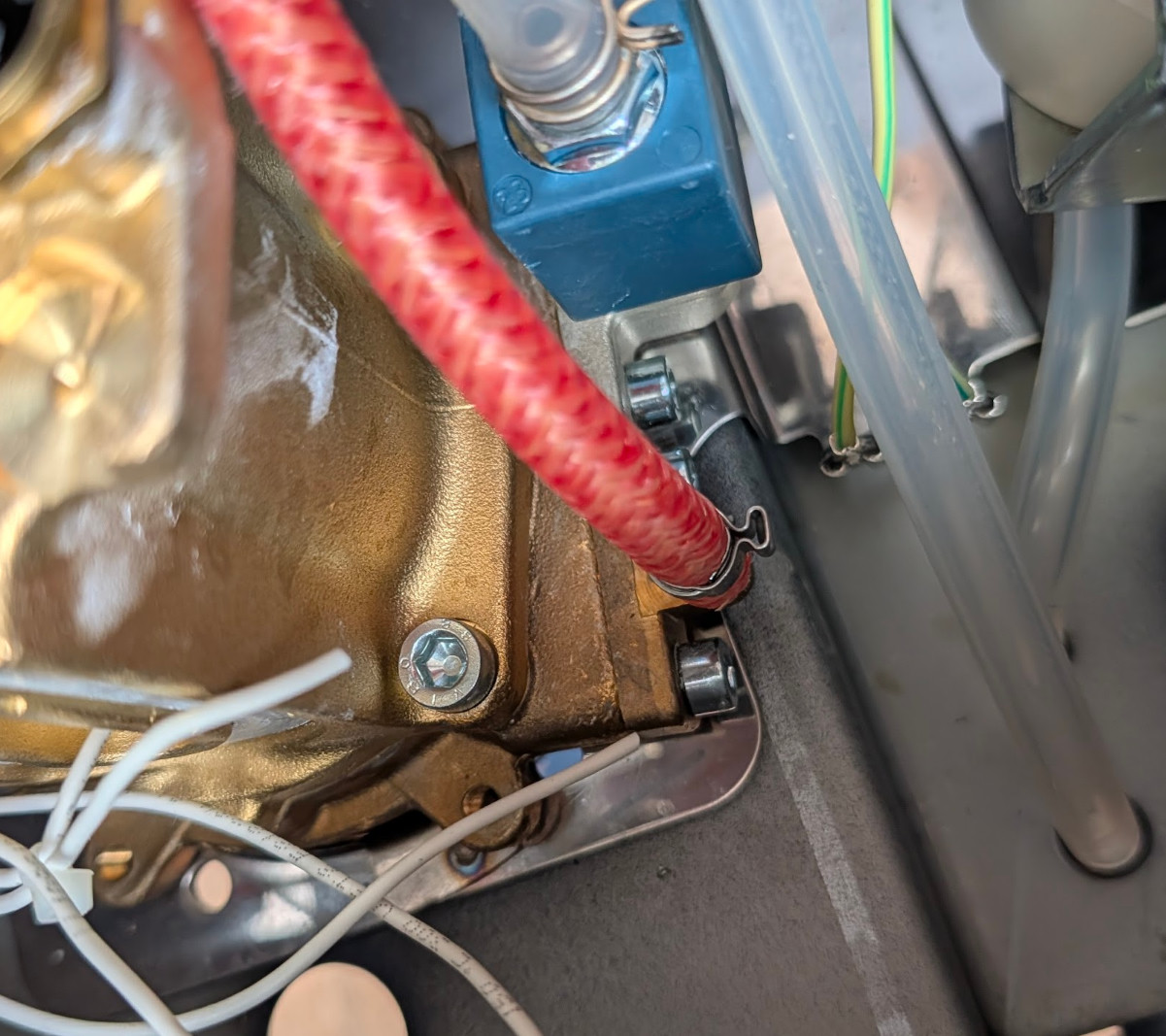
STEP 1 — Locate the pump-to-boiler water line
Trace the water path from the pump to the boiler. Starting from the pump outlet (a rubber or silicone hose exits the pump and goes to the boiler inlet), identify the hose that needs to be intercepted.
The pump has two ports
The pump has an inlet port (water coming in from the tank) and an outlet port (water going out to the boiler). You are intercepting the outlet side — after the pump, before the boiler.
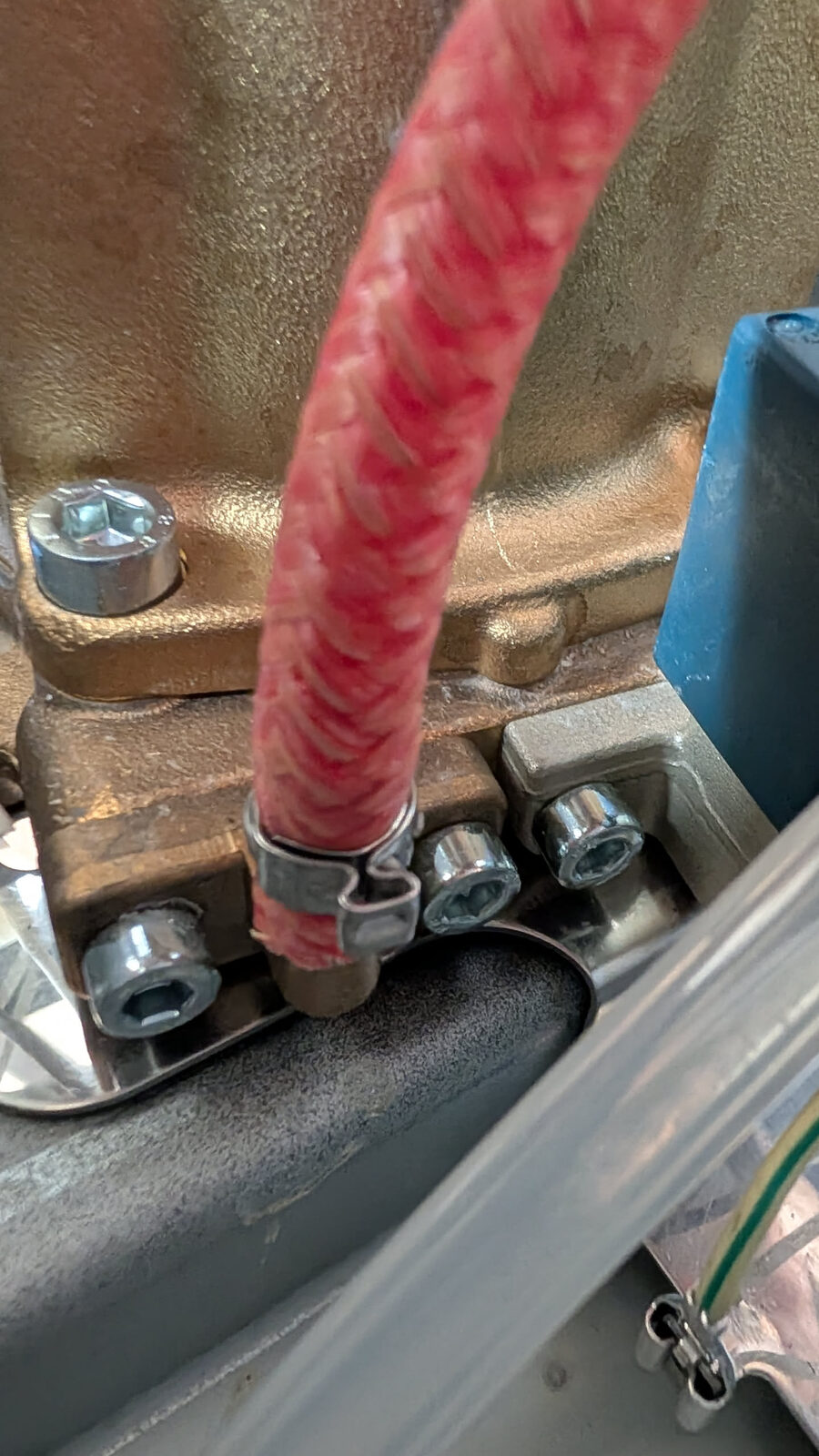
STEP 2 — Install the PTB inline
The PTB goes between the pump outlet and the boiler inlet.
- Release the hose clamps on the pump-to-boiler hose at both ends.
- Remove the hose section.
- Cut the hose if needed to create two segments: pump-to-PTB and PTB-to-boiler.
- Slide hose clamps onto each hose segment.
- Push one end onto the PTB inlet port.
- Push the other end onto the PTB outlet port.
- Tighten the hose clamps — snug but not distorting the hose.
The PTB sensor port (the 1/4" threaded port) should be accessible and pointing somewhere it can be reached by the sensor cable.
STEP 3 — Install the pressure sensor
O-rings missing = guaranteed water leak
The pressure sensor seals via two rubber O-rings that compress against the face of the PTB port. Without them — or if they slip out of position — you will have a high-pressure water leak at 9–12 bar directly inside the machine. This causes water damage and potential electrical shorts.
Do this in order, every time:
- PTFE tape on the thread — 2–3 turns clockwise, starting at the tip. Stretch it lightly as you wrap so it sits into the thread valleys.
- Slide both O-rings onto the body of the sensor (the unthreaded section behind the thread). They must sit in the groove below the thread, not on the thread itself.
- Screw in by hand until the O-rings make contact with the PTB face.
- Tighten with a spanner — ¼ to ½ turn past hand-tight. You are compressing the O-rings, not bottoming out the thread.
If you feel the sensor bottom out on the thread before the O-rings compress: the O-rings are in the wrong position, or the wrong size. Stop and recheck.
Thread type: G1/4 (straight) not NPT (tapered)
Your kit includes a G1/4 sensor. G1/4 threads are straight (parallel). NPT threads are tapered (common in US plumbing). These are not interchangeable.
G1/4 seals with the O-rings. NPT seals with the taper. Using NPT where G1/4 is specified will either not fit or leak.
If sourcing independently: the majority of cheap pressure sensors on Amazon and AliExpress are NPT. Search specifically for "G1/4 pressure sensor 1.2MPa" and verify the listing explicitly says G1/4 (BSP). The thread pitch looks nearly identical to NPT at a glance — check before ordering.
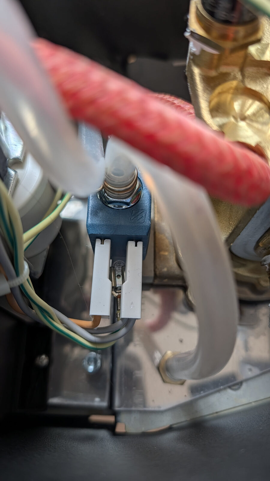
STEP 4 — Route and connect the sensor cable
The pressure sensor has a 3-wire connector:
- VCC — power
- GND — ground
- Signal — the measurement output
DO NOT SWAP VCC AND SIGNAL
Swapping the VCC and Signal wires destroys the sensor instantly and permanently. Check the connector orientation carefully before plugging in.
The connector from your Peak Coffee kit is keyed — it only fits in one orientation. Do not force it.
Connect the pressure sensor cable to the matching connector on the PCB (labelled PRESSURE or SENSOR).
Route the cable so it does not contact the pump (which vibrates) and does not cross hot surfaces.
STEP 5 — Leak test
Before final assembly, do a preliminary leak test:
- Reinstall the water tank.
- Without plugging in the machine: pour water into the tank and observe the PTB area for 60 seconds.
- There should be no drips. If you see water, the hose clamps or sensor O-rings need re-seating.
The definitive leak test happens in Chapter 9 after the machine is powered on, but checking now avoids a mess.