Installation
Chapter 5 of 10 · ~60 minutes · One wire at a time
← Back to: Stage 1–3 Overview
You have built the harness, photographed it flat, and the machine is gutted and unplugged. This is the last stage before first power-on.
MACHINE UNPLUGGED — CONFIRM NOW
Physically remove the mains cable from the wall socket. Verify by pressing the power switch — nothing should happen.
Have ready: Wiring harness · Multimeter · PH2 screwdriver · Small flat-head · Needle-nose pliers · Masking tape + pen · Harness photo on your phone
How this chapter works
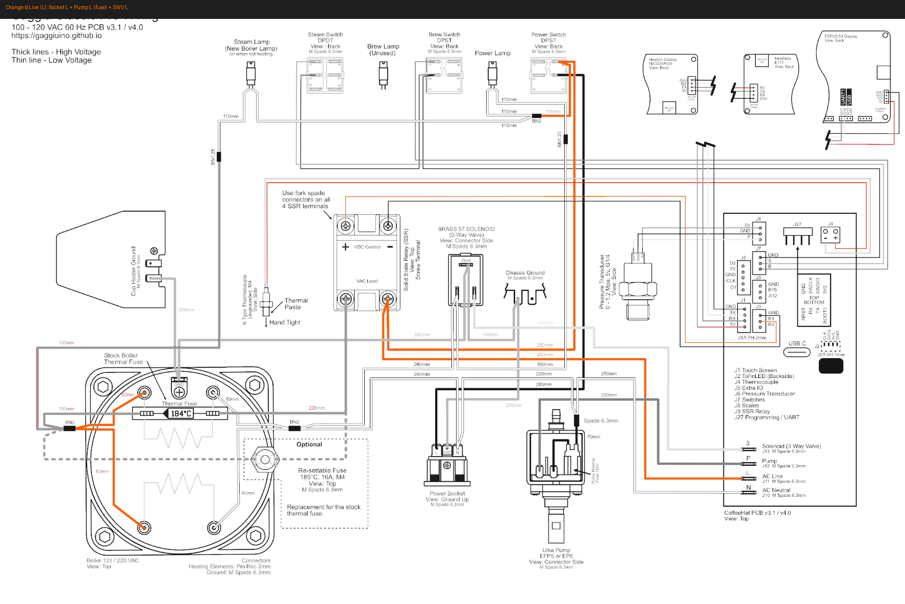
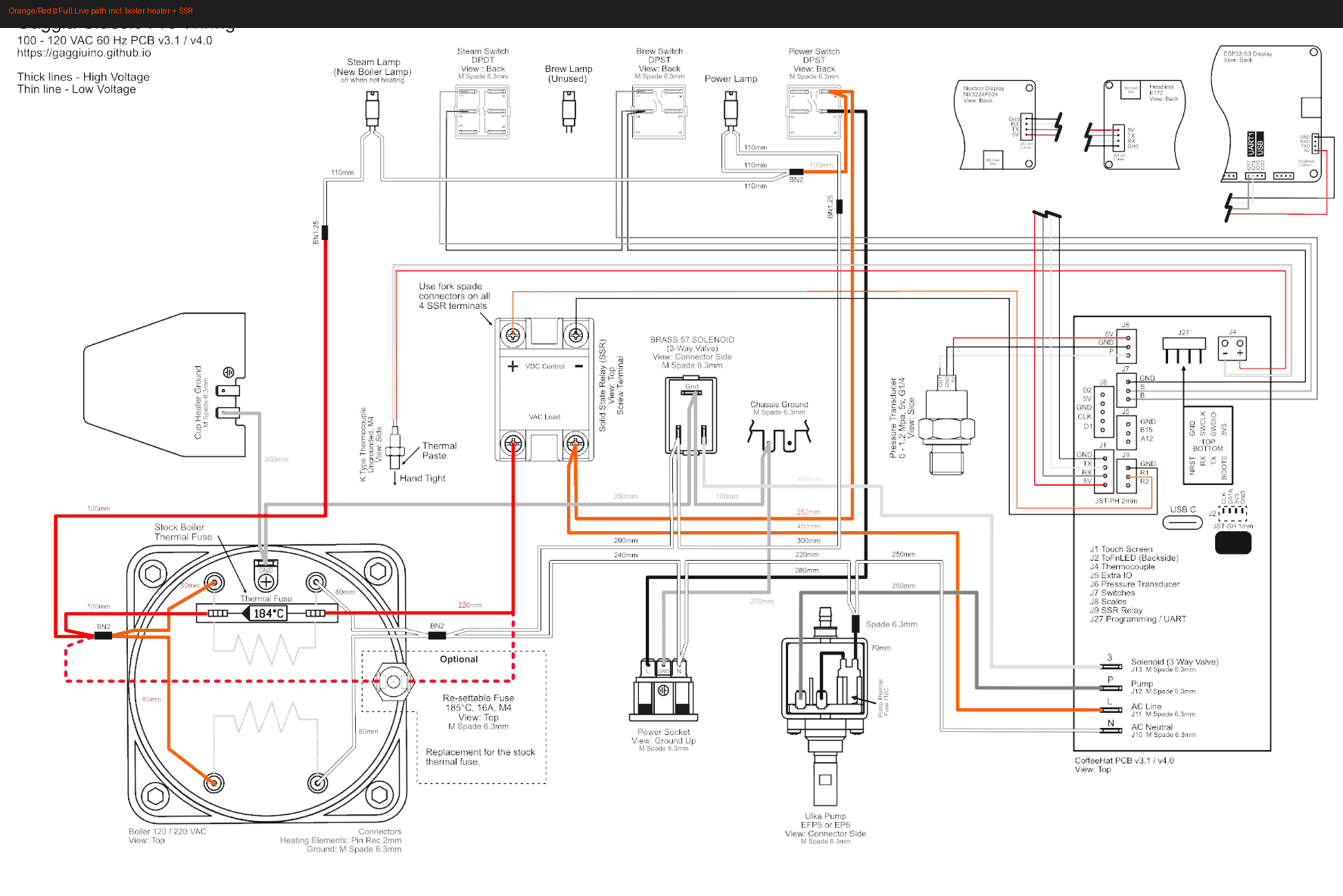
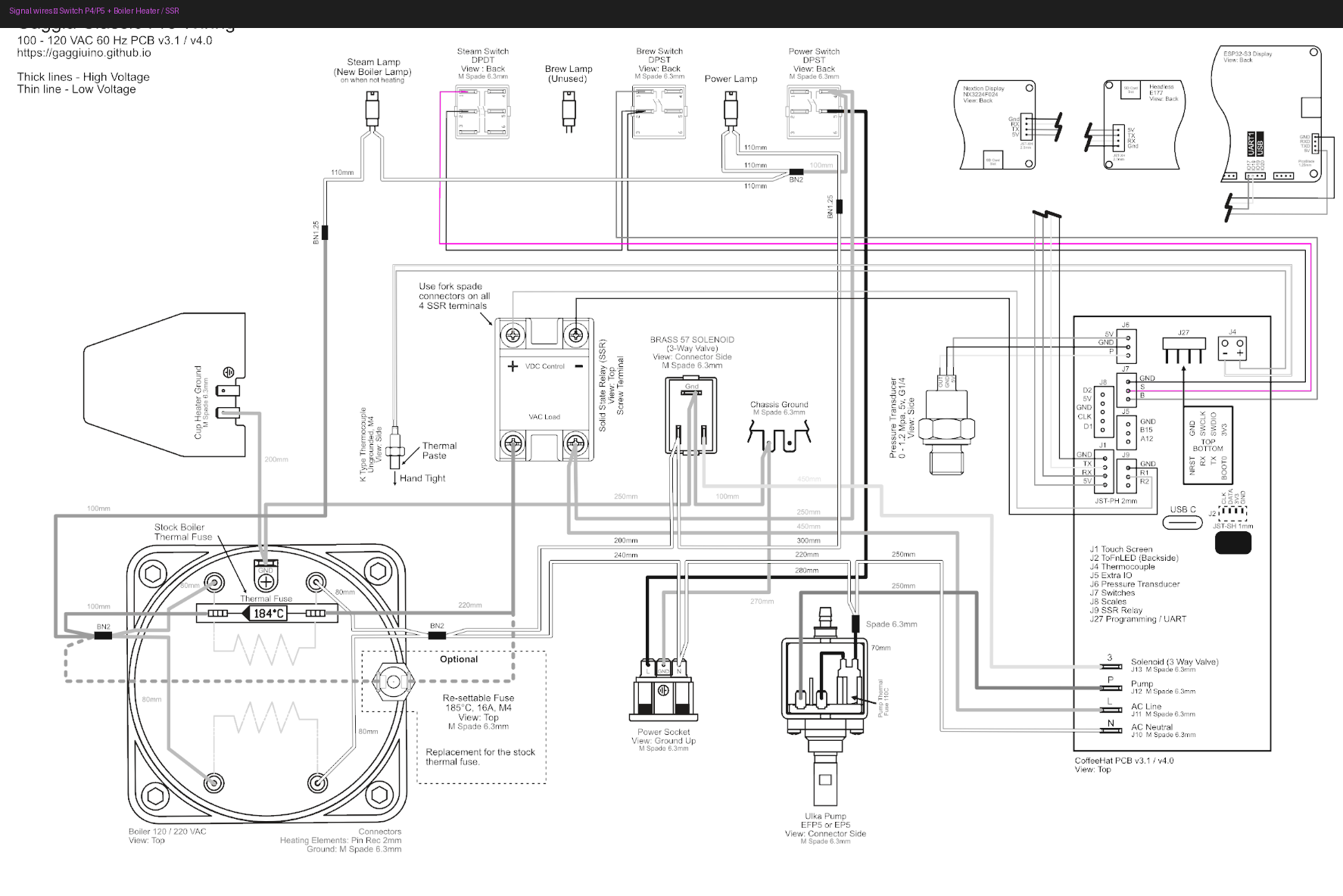
One wire at a time, colour by colour. Each section shows the highlighted wiring diagram for that wire's path, plus reference photos where available. Open the harness diagram photo you took in Stage 3 on your phone — it is your quickest reference for connector types and lengths as you work.
Wire routing
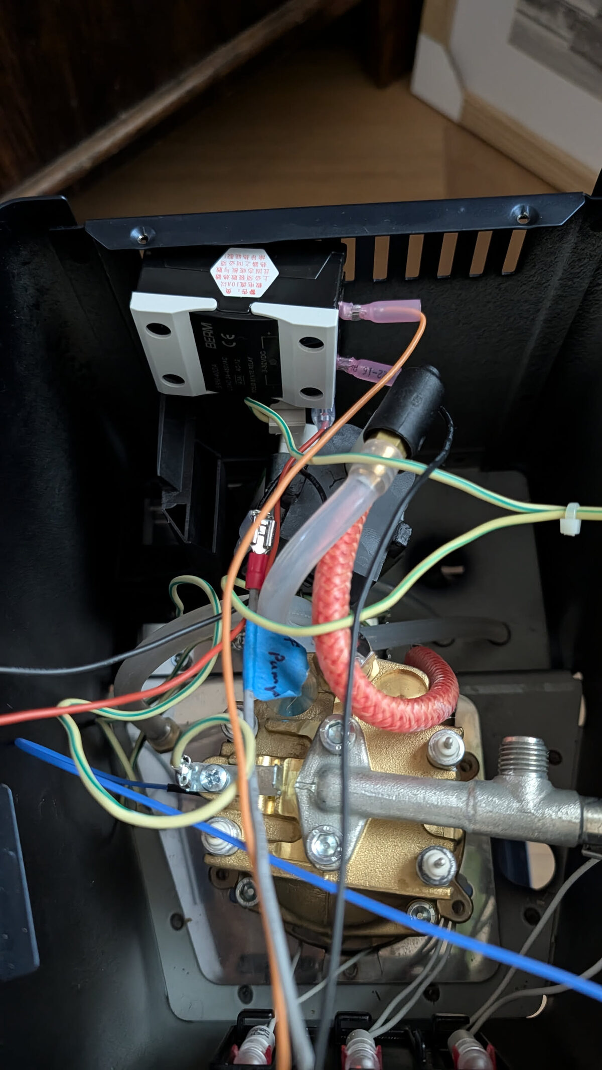
Before connecting anything, understand how the harness runs inside the machine. A wire that crosses in front of the boiler will be heat-stressed; one that blocks the pump is hard to reach later.
| Wire group | Route |
|---|---|
| Socket wires (L, N, G) | From the rear socket, run along the right chassis rail toward the PCB |
| Ground ring terminals | Short runs, stay close to their chassis bolts — don't pull tight |
| Pump wires (L + fuse, N) | Upper-left, from PCB dimmer output down to the pump body |
| Boiler heater wires | 80mm — straight from SSR AC output to boiler terminals, no slack needed |
| 3WV wires (L, N, G) | Bottom centre, short runs from PCB to the valve body |
| Switch wires (P4, P5) | Front panel — route along the front edge down to the PCB |
| Lamp wires | Short runs from PCB lamp outputs to the stub wires at each lamp |
Keep all wires clear of the brew thermostat disc and thermal fuse — both must sit flat against the boiler body with no wire pressure on them.
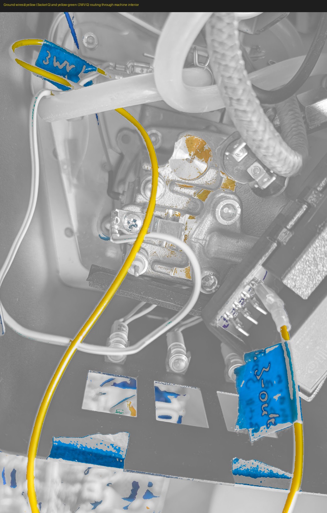
Yellow · Socket G · Earth · 450mm
From: Mains socket — Earth / PE terminal
To: Machine chassis — main frame earth bolt
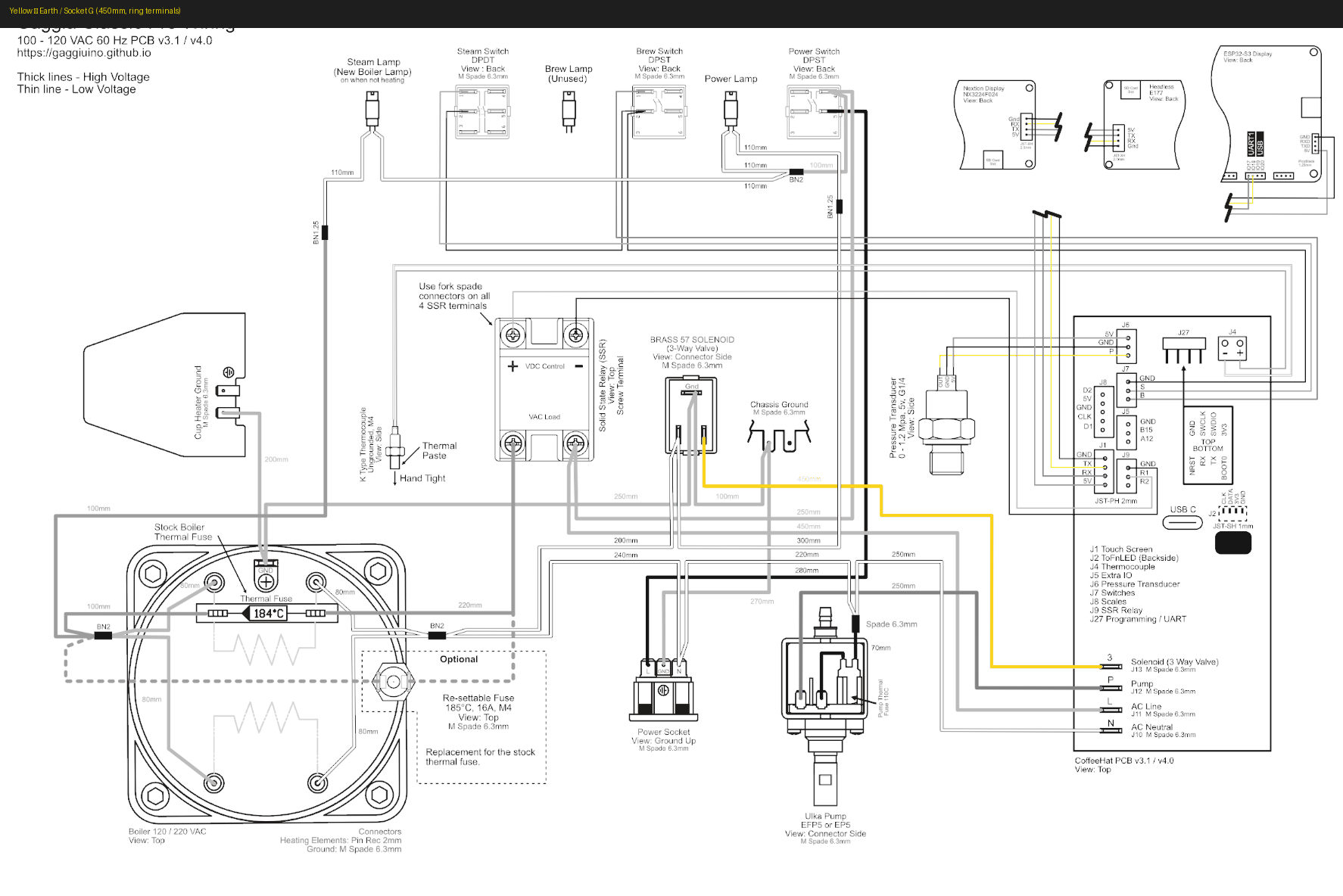
Slide the ring terminal over the earth screw. Tighten firmly with a screwdriver — not finger-tight. Tug test: the wire should not move.
Blue · Neutral (N) · three wires
All blue wires connect to the N side of their component. They trace back to the Wago on Socket N, which bridges to the mains neutral.
Blue · Socket N · 250mm
From: Mains socket — N terminal
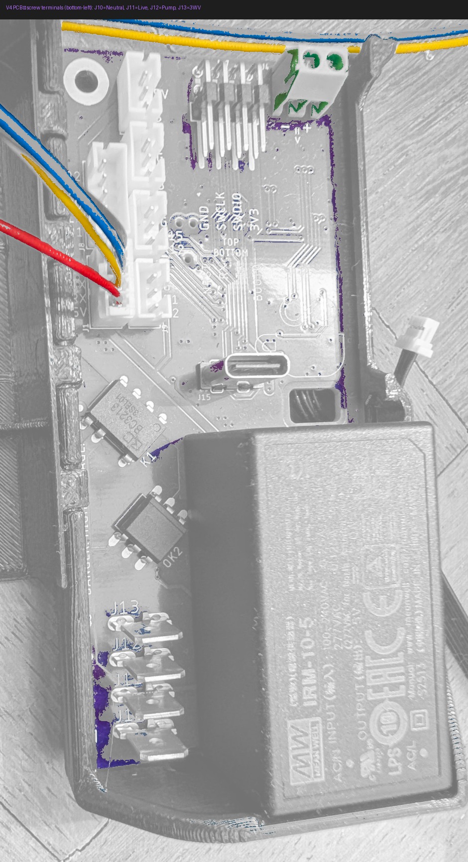
To: PCB — J10 (AC Neutral in) via Wago connector
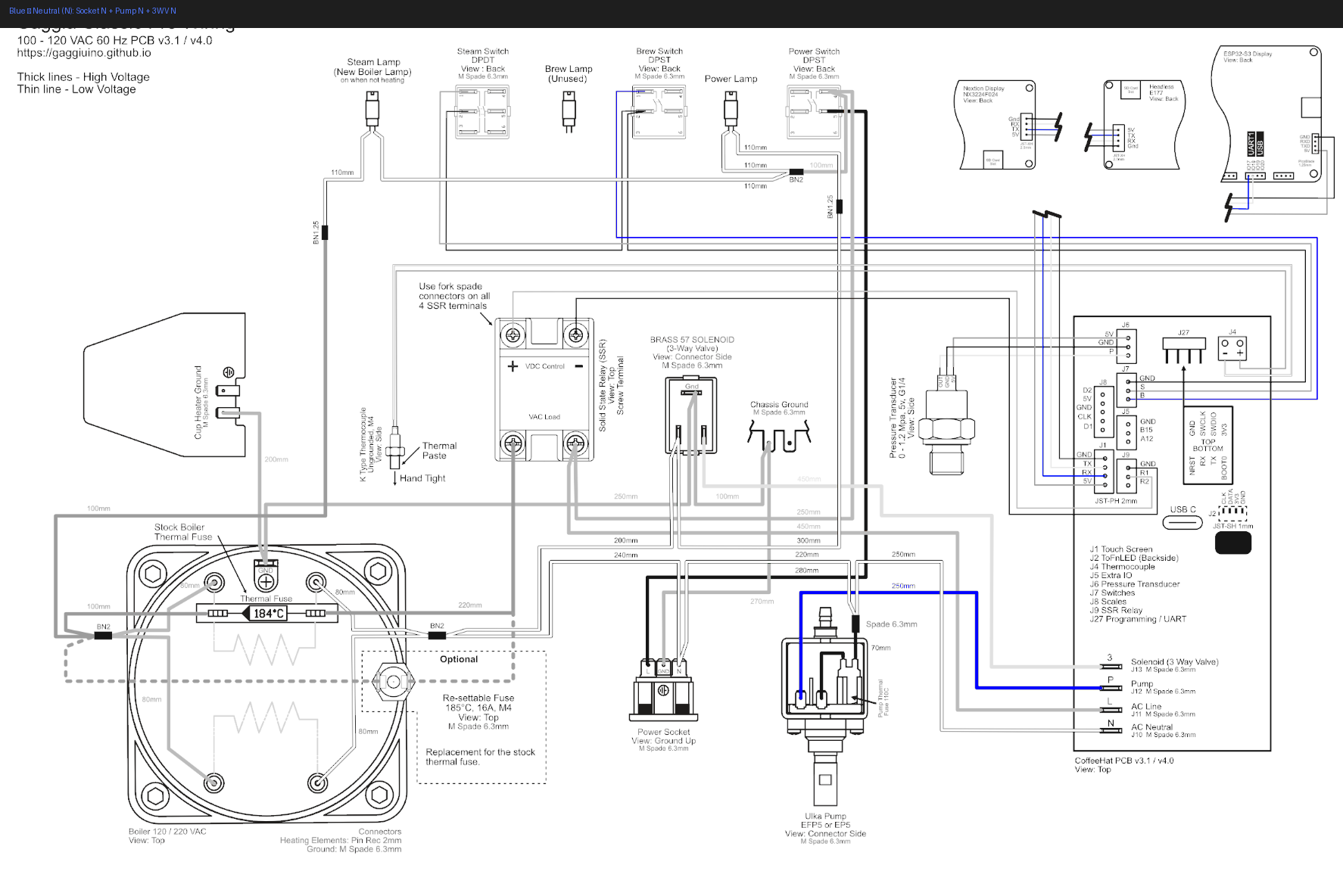
Open the Wago lever, push the original mains neutral wire fully in (visible through the clear body), close the lever. Connect the spade end to the mains socket N terminal.
Blue · Pump N · 250mm
From: PCB — J12 (Pump neutral)
To: Pump — terminal P_b (Neutral side)
Push onto pump terminal P_b — the terminal the original blue wire came from.
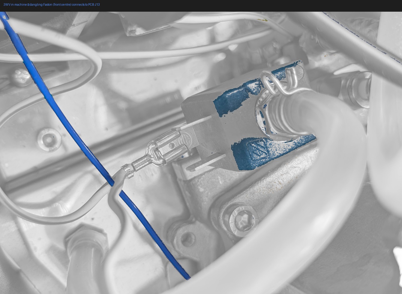
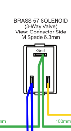
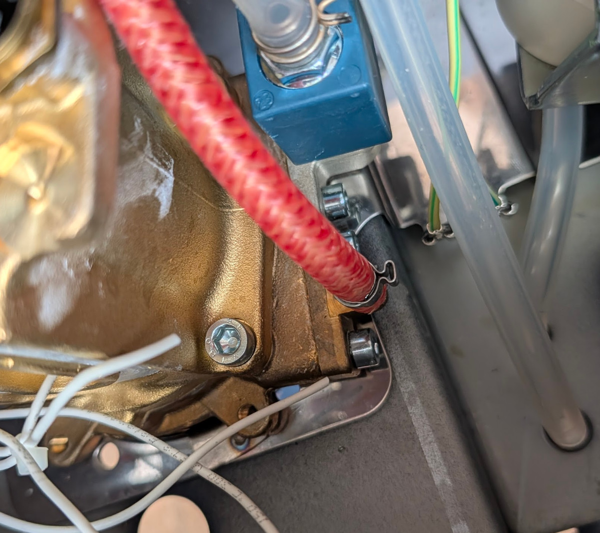
Blue · 3WV N · 200mm
From: PCB — J13 (3WV neutral)
To: 3-way solenoid valve — either terminal (non-polarised)
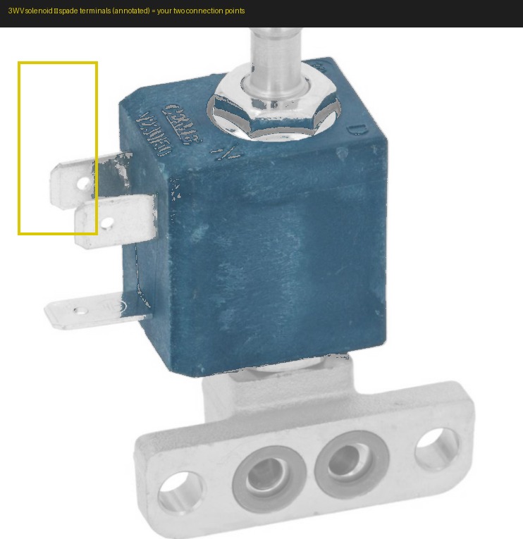
Either terminal on the valve — it is non-polarised.
Why non-polarised? (the coil physics)
The 3WV coil is a simple AC electromagnet. Alternating current produces an alternating magnetic field — the internal plunger is pulled on every half-cycle regardless of which spade receives Live and which receives Neutral. No rectifier, no diodes, no polarity requirement on the two parallel spades.
Ground is different. The third terminal — the top horizontal spade on the valve body — must connect to the teal ground wire (3WV G, 100mm, installed in the ground section below). Ground is not optional and cannot be swapped with the power spades.
Polarity only matters for DC solenoids with built-in electronics such as LEDs or flyback protection diodes. The Gaggia Classic 3WV is a plain AC coil — this is not one of those.
Orange · Live (L) · three wires
Verify every orange wire against the wiring diagram before connecting — Live wires are permanently energised when the machine is plugged in
Orange · Socket L · 280mm
From: Mains socket — L terminal
To: PCB — J11 (AC Line in)
Angled spade fits the socket better
The mains socket L terminal is recessed at the back of the machine. An angled (L-shaped) 6.3mm Faston spade seats here with much less effort than a straight one.
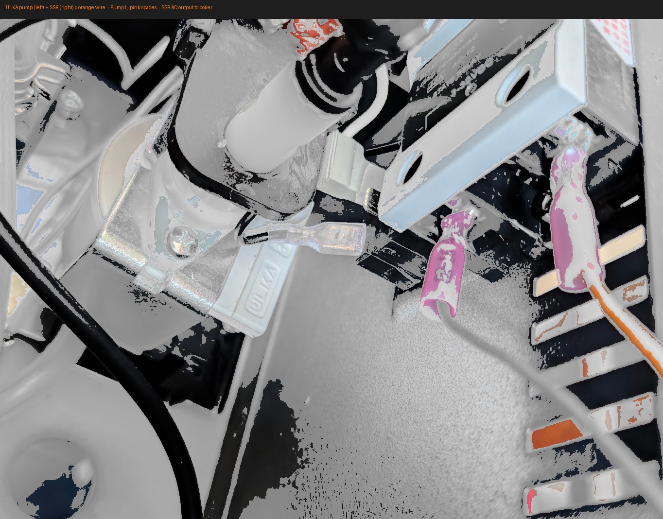
Orange · Pump L · 220mm · inline fuse
From: PCB — J12 (Pump Live)
To: Pump — terminal P_a (Live side)
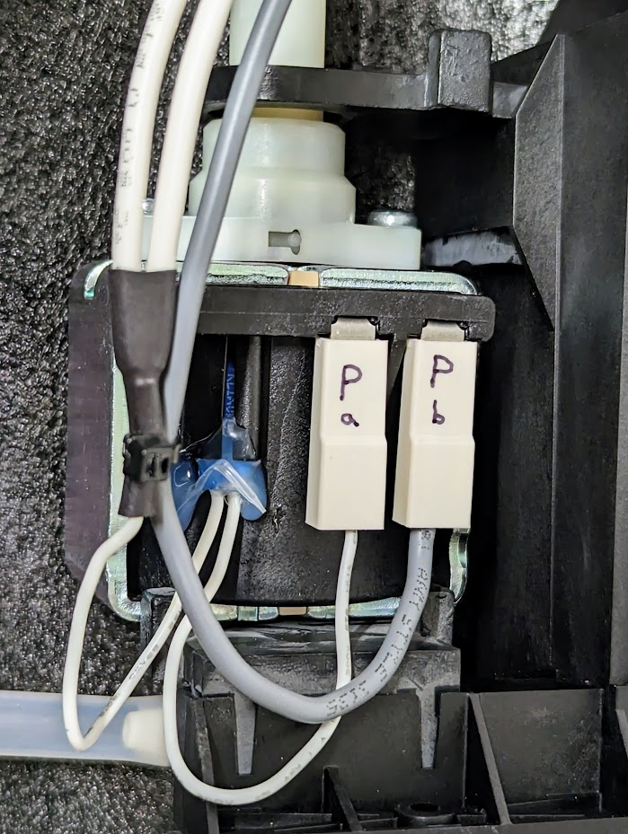
Keep the inline fuse body accessible — do not bury it under other wires. You may need to replace it in future.
Orange · 3WV L · 240mm
From: PCB — J13 (3WV Live)
To: 3-way solenoid valve — either terminal (non-polarised)
Either parallel spade works for this wire — see the coil physics note in the 3WV N section above.
Boiler heater wires · 80mm pair
Uninsulated spade terminals only here — cover immediately with high-temp silicone tape (≥200°C)
From: SSR — AC output terminals
To: Boiler — heater terminals (two, non-polarised)
Inline: Thermal fuse — must sit flat against boiler body
Angled spades for the boiler terminals
The boiler heater terminals are in a tight corner. Uninsulated angled (L-shaped) 6.3mm spades seat much more cleanly than straight ones — same crimping technique, same high-temp tape after. See the tip in Stage 2.
Thermal fuse must contact the boiler body — clip it flat, no gap
White · Lamp wires
Heater Lamp · 100mm · 4.8mm spade — PCB lamp output → heater lamp stub
Power Lamp · 110mm · 4.8mm spade — PCB lamp output → power lamp stub
The stubs are the short wire pieces left attached to each lamp after Stage 2 trimming. You connect to the stub, not directly to the lamp body.
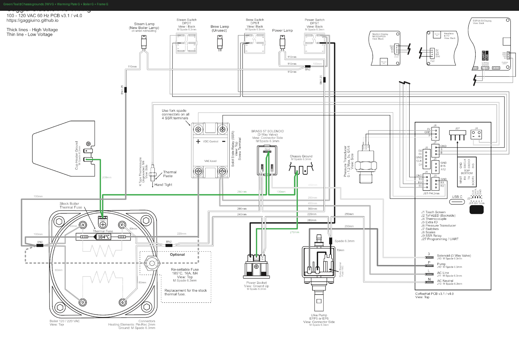
Teal · Chassis ground ring terminals
From: PCB — ground terminal group
To: Machine chassis — same bolts as factory ground wires (stack alongside, do not replace)
| Wire | Length | Bolt |
|---|---|---|
| 3WV G | 100mm | Near 3-way valve |
| Warming Plate G | 200mm | Warming plate |
| Boiler G | 250mm | Near boiler |
| Frame G | 270mm | Main chassis frame |
Tighten all ring terminals with a screwdriver. Verify continuity from each to mains earth with multimeter — each should beep.
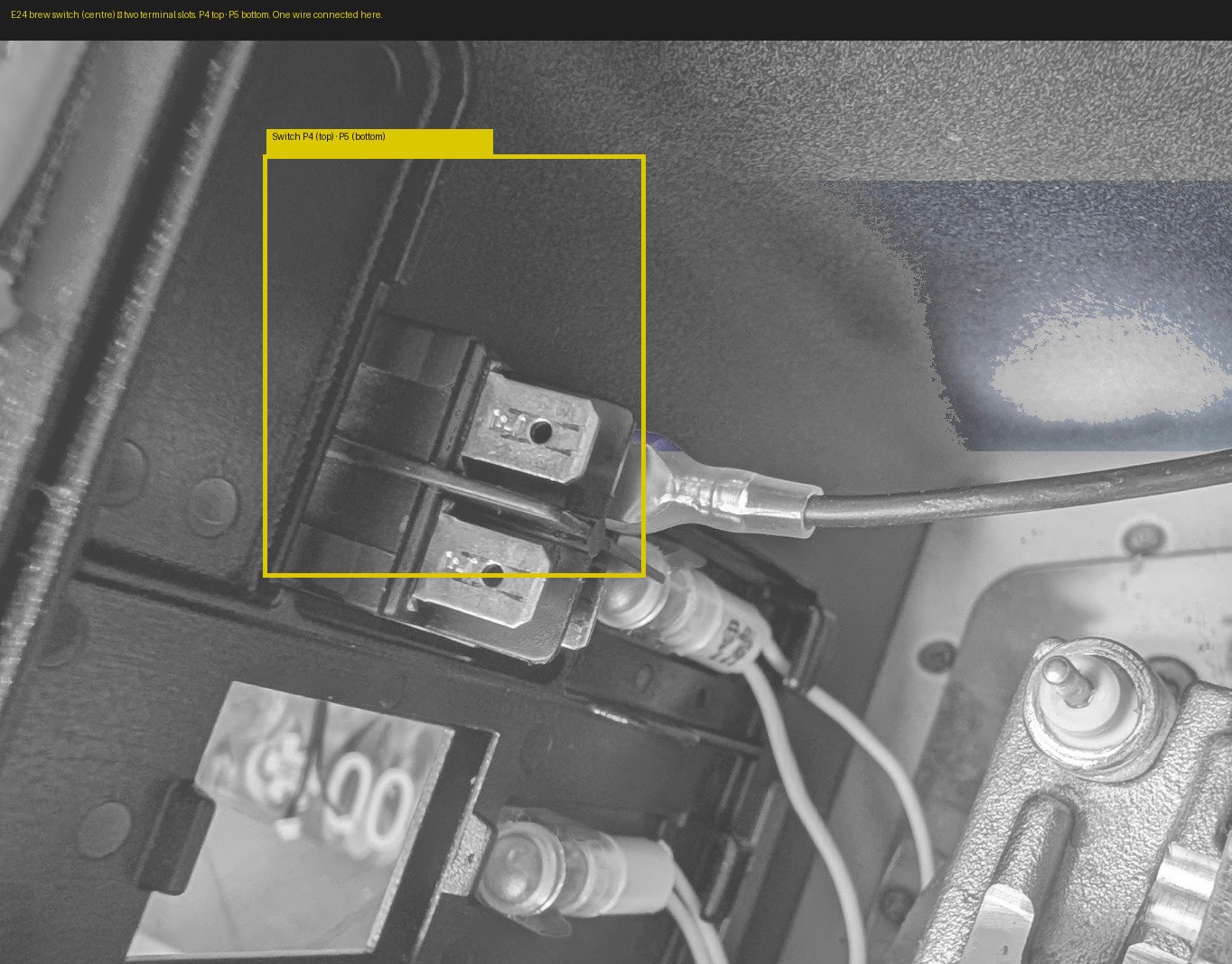
Switch wires · P4 + P5 · do this last
Wrong terminal = melted wire insulation and possible fire
The E24 switch has permanently-live terminals that look identical to switched terminals. Count from pin 1 on the switch face. Cross-reference the wiring diagram. Do not guess.
Why last: Once every other wire is routed and dressed, the harness is settled and out of the way. You can work on the switch connection slowly and deliberately with nothing loose to bump or accidentally short against. Doing it while the rest of the harness is still unsettled means more things in motion near the most dangerous terminals in the machine.
Switch L in · P5 · 300mm — PCB → switch input terminal
Switch L out · P4 · 100mm — switch output terminal → PCB
Angled spades work better at the switch terminals
The brew switch terminals are behind the front panel — limited clearance. Angled (L-shaped) 6.3mm Faston spades push on straight-in and sit flat behind the panel without stressing the connector.
Label both wires with masking tape before connecting: P4 — out and P5 — in.
Final check
- Socket G ring terminal cannot be pulled off the earth screw
- Socket N Wago lever closed — original neutral wire fully inside
- All spade connectors fully seated — no half-inserted connectors
- Pump inline fuse accessible and not buried
- Boiler heater spades covered with high-temp tape
- Thermal fuse flat against boiler body — no gap
- Switch P4/P5 positions verified against wiring diagram
- All ring terminals tightened with screwdriver
- Multimeter continuity on every ground ring terminal
You're 55% done.
The lesson: take it wire by wire, and the machine will tell you when you've got it right.
Next: Chapter 6 — Pressure Transducer ([PTB](../../glossary.md#ptb))