Chapter 4 — E24 Specific Mods
Chapter 4 of 10 · ~45 minutes · E24 / Eco PCB machines only
This chapter is E24 and Eco PCB machines only
If your machine was manufactured before 2023, you likely have a non-Eco machine and can skip this chapter. Check the label on the back of your machine for the model number RI9481 (E24) or verify you have the Eco PCB as identified in Chapter 3.
The E24 has two differences from older Gaggia Classic Pro models that require extra steps. Both are straightforward. Neither requires special tools.
Why the E24 needs these modifications
For this chapter, prepare:
- Phillips screwdriver PH2 (1×)
- Small flat-head screwdriver, 2–3mm tip (1×)
- Needle-nose pliers (1×)
- The machine, unplugged from the wall
UNPLUG THE MACHINE NOW
Confirm the power cable is physically disconnected from the wall socket before touching anything inside the machine. The machine must remain unplugged for the entire duration of this chapter.
Part A — Power Switch Spring Removal
Why this is needed
The power switch on the E24 is monostable: it springs back to the off position the moment you release it. This is an EU energy regulation requirement — the machine cannot stay powered if you stop pressing the switch.
Gaggiuino requires the machine to power on and stay on while it manages a 10–15 minute warmup phase to reach thermal equilibrium. A switch that springs off the moment you release it makes this impossible.
The fix is removing one spring from inside the switch housing. The switch will then latch in the on position (like a normal light switch) and require a second press to turn off.
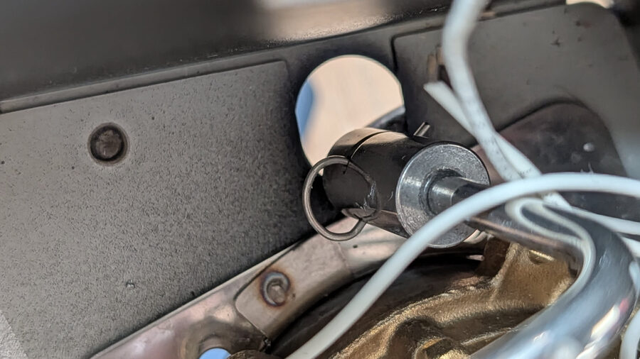
STEP 1 — Locate the power switch
The power switch is the large rectangular rocker switch at the front of the machine. It has the power symbol on it (the circle with a vertical line).
The switch is accessible from inside the machine with the top panel removed (done in Chapter 3).
From inside, look at the back of the switch. You will see the switch body and, if you look carefully at the sides, a small gap where the spring mechanism is visible.
STEP 2 — Remove the switch from the machine
You may not need to fully remove the switch
On some E24 units, you can access the spring without removing the switch from its housing. Try first by looking through the side gap with a torch. If you can see and access the spring directly, do that instead.
If you need to remove the switch:
- Look for the two plastic tabs on the left and right sides of the switch housing (the part that clicks into the front panel).
- Use your small flat-head screwdriver to press in one tab while pulling the switch body backward (into the machine interior).
- The switch should release from the panel.
Do not pull on the wires. Hold the switch body.
STEP 3 — Identify the spring
Hold the switch body so you can see inside the mechanism. The switch has a rocker mechanism and, at the bottom of the travel, a small return spring.
The switch has three springs: - Two that are part of the normal switching mechanism — leave these alone - One that causes the monostable return — this is the one to remove
The return spring sits at one end of the rocker pivot. It is typically a small coil or leaf spring at the lower/rear edge of the switch body.
For experienced builders — which spring exactly
The monostable spring is the one that stores energy when the switch is pressed and releases it to push the rocker back. It is loaded in compression when the switch is in the 'on' position. If you press the rocker and feel spring resistance returning it to off, that is the one.
STEP 4 — Remove the return spring
Use your needle-nose pliers to grip the spring and pull it out.
Do not lose the spring
Set it aside in a small container or tape it to a piece of paper. If you want to sell or restore the machine later, reinstalling the spring returns it to stock behaviour.

STEP 5 — Verify the switch now latches
Press the switch rocker to the on position. Release it.
Expected result: The switch stays in the on position. It does not spring back.
Press it again to off.
Expected result: The switch clicks off and stays off.
If it still springs back, check whether the correct spring was removed. The other springs in the mechanism should stay in place — they provide the tactile click, not the return force.
STEP 6 — Reinstall the switch
Press the switch back into its front panel housing until both tabs click into place.
Tug gently on the switch body. It should not pull free.
Part B — Eco PCB Bypass
Why this is needed
The Eco PCB (the small green PCB you identified in Chapter 3) includes an automatic shutoff timer. After 20 minutes of idle, it cuts power to the machine.
This interferes with Gaggiuino in two ways: 1. The machine shuts off during the warmup period if you walk away 2. In some configurations, the Eco PCB's switching logic conflicts with Gaggiuino's boiler control
The bypass is a physical bridge — a short wire or jumper between two pins on the switch connector — that bypasses the timer logic.
STEP 7 — Locate the Eco PCB connector
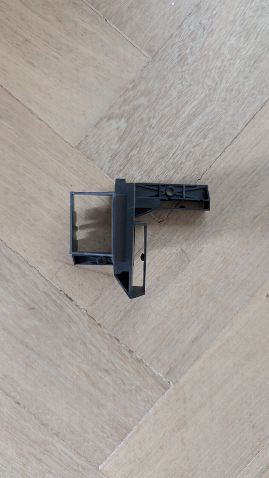
The Eco PCB is the small green board you found in Chapter 3. It has a white plastic multi-pin connector with multiple wires going to it (this is the monoblock connector mentioned in the Before You Start chapter).
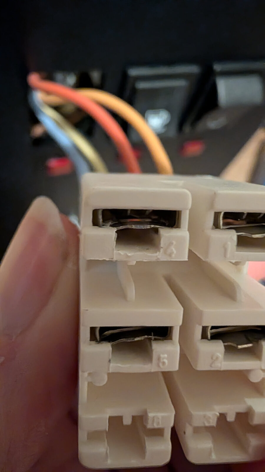
The connector pins are numbered on the housing face (look for moulded numbers beside each slot). The ones you care about:
- C.1 — Brew switch signal wire (typically brown or grey)
- C.2 — Brew switch signal return (typically brown or grey, same colour as C.1)
- C.3 — (timer/control — leave untouched)
- C.4 — Live supply wire from brew switch (brown, heavier gauge)
Verify C.1 and C.2 before bridging — do not guess
The pin numbers are moulded into the plastic housing face in small raised digits. Hold the connector face-up under a bright light and count from pin 1. On some E24 units the numbering runs left-to-right; on others right-to-left depending on which face you are looking at. Count twice, bridge once.
If you cannot read the numbers, trace the brew switch wires: C.1 and C.2 both connect to the brew switch. C.4 is the thick brown wire from the Live supply — do not bridge to C.4.
STEP 8 — Disassemble the monoblock connector
Do not cut the wires
Many builders cut the monoblock connector wires at this point. This is wrong. You need to push the individual pins out of the plastic housing — they can then be reinserted in different positions or individual wires replaced.
The monoblock connector is a plastic housing with individual crimp pin terminals inside. Each pin has a small plastic locking tab.
To remove a pin:
- Look at the front face of the connector housing (the side where wires enter).
- Insert your small flat-head screwdriver (2–3mm tip) into the slot beside the pin you want to remove.
- Press gently inward to depress the locking tab — about 1mm of movement.
- While holding the tab down, pull the wire from the back of the connector.

The pin slides out from the rear.
Practice on a pin you don't need to modify first
The technique takes a few tries to feel right. The movement is small — you are pressing a 1mm plastic tab, not prying the connector apart.
STEP 9 — Bridge C.1 to C.2
The eco bypass requires that pins C.1 and C.2 in the connector be permanently bridged together.
Two ways to do this:
Option A — Jumper wire (easier, fully reversible) - Take a short piece of wire (any colour, ~5 cm) - Strip both ends to expose 5mm of bare wire - Crimp both ends to female crimp pin terminals (the same type as the connector uses) - Insert both ends into positions C.1 and C.2 in the connector housing
Option B — Splice the wires (cleaner) - Remove both C.1 and C.2 wires from the connector - Use a wago lever connector or butt splice connector to join them - Reinsert them together into one position
What does bridging C.1 to C.2 actually do?
The Eco PCB uses the brew switch signal to detect activity and reset its shutoff timer. By permanently bridging these two pins, the circuit sees continuous activity — the timer never starts.
This does not affect brewing function. The brew switch still operates normally through the separate circuit path.
STEP 10 — Verify the bypass
After making the bridge:
- The connector should still have all other wires in their correct positions
- The bridge should be secure — tug gently on the jumper/splice. It should not come loose.
Checkpoint — E24 Mods Complete
Before moving on, verify:
- Power switch latches in the on position and stays latched when released
- Power switch clicks off and stays off when pressed again
- C.1 and C.2 are bridged, connection is secure
- No wires were cut without a proper splice or reconnection
- All other connector pins are in their correct positions
Chapter 4 of 10 complete. The E24-specific mods are done. Next is wiring — the longest chapter, typically 3–5 hours. Take a break before you start it.