Chapter 1 — Bill of Materials & Kit Check
Chapter 1 of 10 · ~30 minutes · No tools needed
Before touching your machine, verify every component you have and identify every tool and material you will need. A missing part mid-build costs an hour. A missing tool mid-session costs an evening.
This chapter covers two things: what came in your kit, and what you need to source yourself.
STEP 1 — Clear your workspace and unbox
Find a large, clean, well-lit table. Lay out a piece of white paper or a light-coloured cloth — small components are much easier to find against a light background.
Remove everything from your Peak Coffee GEN3 V4 Complete Kit box and place each bag beside the others. Do not open any bags yet.
STEP 2 — Identify the main PCB
Find the bag labelled V4 PCB or Main Board. Inside is the heart of the build.
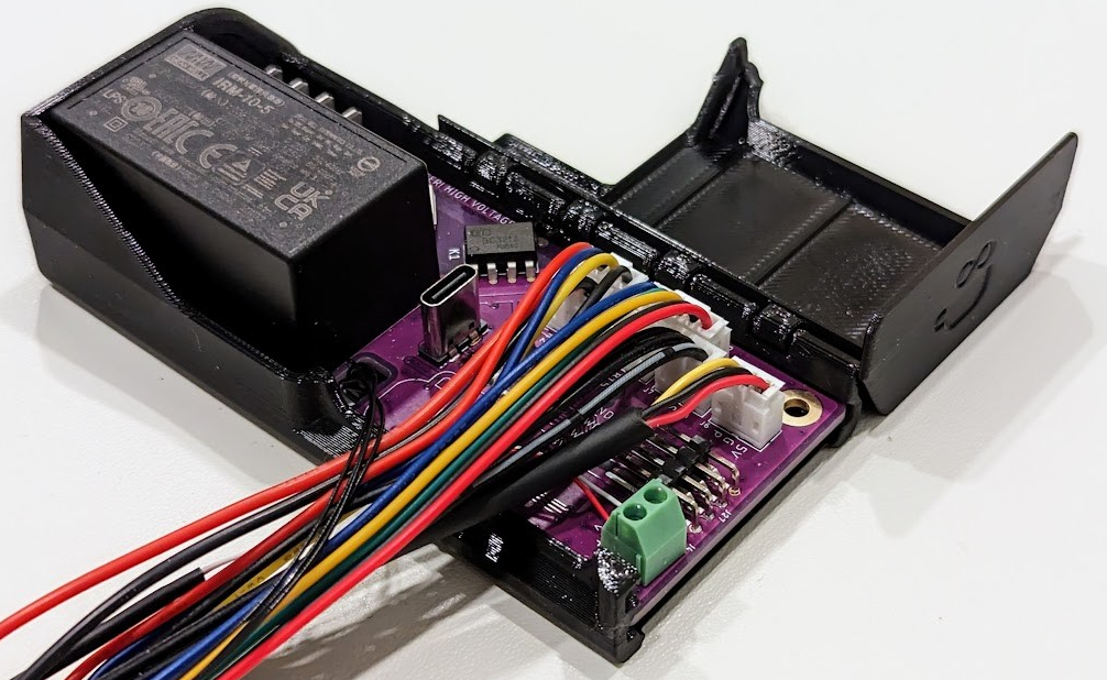 Image: Gaggiuino project — all rights reserved by contributors
The V4 PCB is a circuit board roughly the size of a credit card. It has:
- Two chips visible on the front (the larger STM32U585 and the smaller ESP32)
- A row of screw terminal connectors along one edge (labelled L, N, PE, DIMMER, SSR, etc.)
- A USB-C port on one short edge (used for firmware flashing)
- A 2-pin connector labelled
HMIfor the touchscreen - Multiple labelled connectors for sensors
Verify you have:
- V4 PCB (1×) — circuit board, pre-assembled, gold-plated connectors
- 4.3" HMI touchscreen display (1×) — rectangular screen, pre-flashed, two ribbon cable connectors
- Screen cable (1×) — flat ribbon cable, approximately 45 cm
- USB-C cable (1×) — for firmware flashing (if doing Path A firmware)
Pre-flashed means what it says
The V4 PCB and HMI screen from Peak Coffee come with Gaggiuino firmware already installed. If you purchased the Complete Kit and do not want to manage firmware yourself, you can skip the manual firmware flashing steps in Chapter 8. Both paths are covered.
STEP 3 — Identify the sensors
These three sensors measure temperature, pressure, and thermal safety. All three are installed inside the machine.
Verify you have:
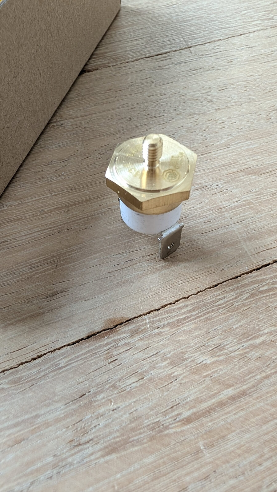
- K-type thermocouple probe (1×) — small cylindrical metal probe with an M4 threaded tip (the thread is the small screw thread at the copper end) and two thin wires exiting the back. This replaces the stock brew thermostat.
- Pressure sensor (1×) — a short cylindrical brass body with a G1/4 threaded port on one end and a 3-pin connector on the other. Labelled 0–1.2 MPa.
- Thermal fuse (1×) — a small ceramic cylinder with two wire leads and spade connectors at both ends. This mounts against the boiler as a safety cutout.
- Two O-rings (2×) — small black rubber rings, about 8 mm diameter. They slide onto the pressure sensor body behind the thread and create a watertight seal between the sensor and the PTB. Installed in Chapter 6.
Thermocouple — do not bend the probe
The thermocouple probe tip is fragile. Do not bend the metal probe at the copper end. Handle by the cable body.
What does the thermocouple actually do?
The stock Gaggia Classic Pro uses a bimetallic thermostat — a disc that physically bends when hot and breaks the heating circuit at a fixed temperature. This is imprecise and cannot be adjusted without replacing the disc.
The thermocouple is a different type of sensor: it produces a tiny voltage proportional to its temperature. The PCB reads this voltage 10 times per second and adjusts the boiler heater in real time. This is how the machine maintains ±0.5°C stability instead of ±5°C.
STEP 4 — Identify the SSR
The SSR (Solid State Relay) is the component that controls the boiler heater. It replaces the mechanical relay inside your machine.
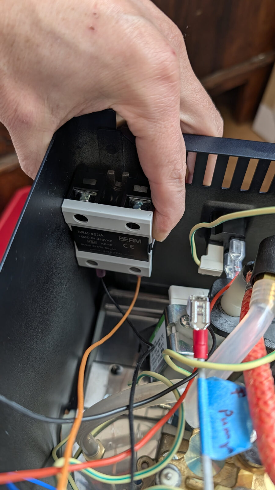
Verify you have:
- SSR DA40 (1×) — a flat rectangular block approximately 80×50mm, with a red flip-safety cover on the top. It will have screw terminals on both the AC (high voltage) and DC (control) sides. The brand marking should be visible.
- M4 screws (2×) — for mounting the SSR to the chassis
Counterfeit SSR warning — inspect yours now
Counterfeit SSRs are common. A counterfeit labelled as 40A will fail at 10A, creating a fire hazard.
Your SSR from Peak Coffee is genuine. This warning is for anyone sourcing components independently. Genuine units have clear brand markings, solid casing, and are heavier than counterfeits.
If you purchased your kit from Peak Coffee, proceed.
Why does the SSR mount to the chassis?
The SSR dissipates heat as it switches the boiler heater on and off. It uses the metal chassis of the machine as a heatsink. Mounting it to metal is not optional — an SSR running without a heatsink will overheat and fail within minutes of use.
STEP 5 — Identify the wiring harness
The wiring harness is the most complex-looking component in the kit, and the one that intimidates most people. Once you understand it, it is actually the most satisfying part.
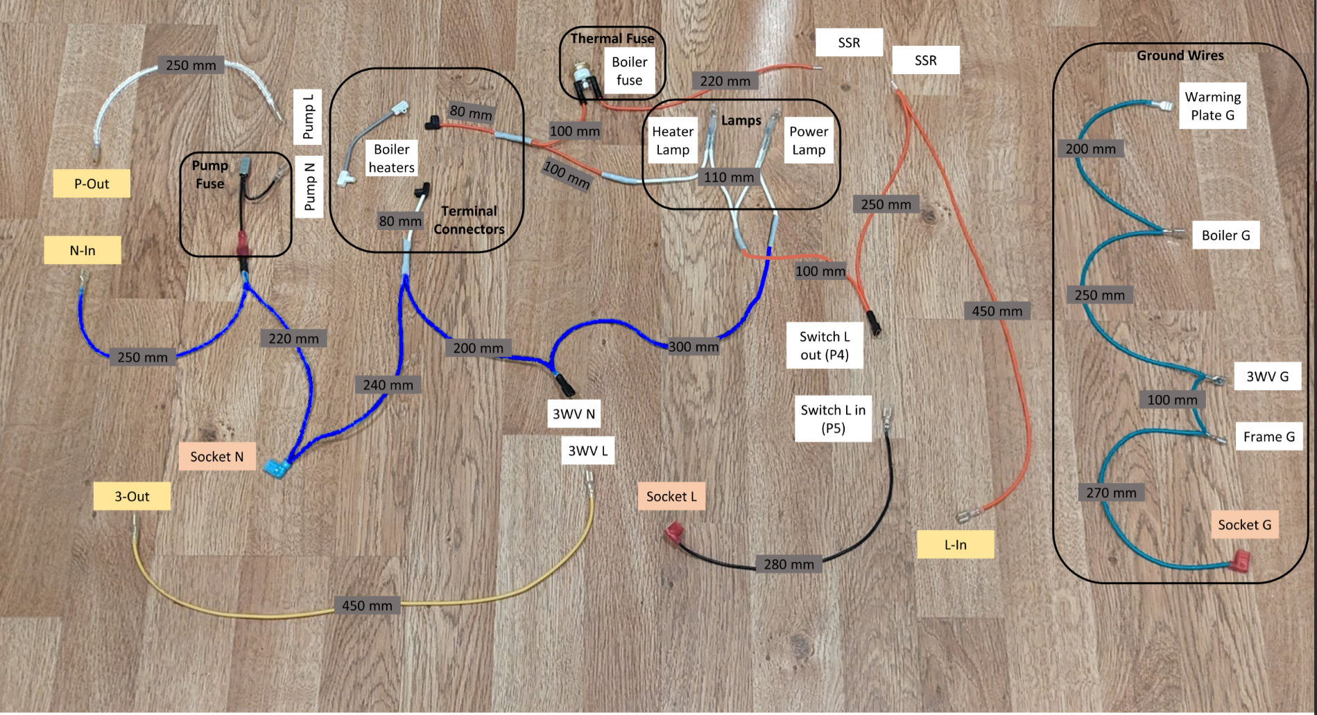
Left: Pump group (blue/orange) + boiler heater terminals · Centre: [3-way valve](../../glossary.md#three-way-valve), lamps, switch wires · Centre-top: Thermal fuse · Right: SSR wires + ground wire group (teal/yellow)
Your harness is a set of pre-made wire runs. Every wire is pre-cut to length and pre-terminated with the correct connector type. You do not make any custom wires.
The colour coding is deliberate and consistent:
| Colour | Meaning |
|---|---|
| Blue | Neutral (N) — one side of the AC circuit |
| Orange/Red | Live (L) — the other side of the AC circuit |
| Teal/Green | Ground (Earth, PE) — safety ground |
| Yellow | Also Ground — long ground runs |
Verify you have (count the groups):
- Pump wiring group: 2 wires (Pump L, Pump N) with pump fuse inline — blue/orange
- Boiler heater group: 2 wires (Boiler heater connectors) — blue/orange with flat spade ends
- 3-way valve group: 2 wires (3WV N, 3WV L) — blue/orange
- Switch wiring: 2 wires (Switch L in, Switch L out) — orange/black
- Lamps: 2 wires (Heater Lamp, Power Lamp) — blue/orange
- Socket wires: 3 wires (Socket L, Socket N, Socket G) with spade connectors
- Thermal fuse wires: included inline in boiler circuit
- Ground wires group: 4 wires (Warming Plate G, Boiler G, 3WV G, Frame G) — teal
- Long ground wire (Socket G) — yellow, 450 mm
Your harness photo is your reference
If you built your harness yourself, the photo you took of it laid flat (wires spread out with all connectors visible) is your single most useful reference for the installation chapter. Keep it accessible on your phone.
If you received a pre-made harness from Peak Coffee, refer to the Peak Coffee wiring diagram PDF included in the box.
STEP 6 — Identify the pressure hardware
The Pressure Tube Block (PTB) is a CNC-machined stainless steel component that creates a T-junction in the water path between the pump and the boiler.
Verify you have:
- PTB (Pressure Tube Block) (1×) — small stainless steel block with 3 ports (in, out, and a 1/4" sensor port)
- Pressure hose (1×) — approximately 25 cm of food-grade silicone hose
- Hose clamps (4×) — small stainless steel worm-drive clamps
STEP 7 — Identify the Complete Kit extras
The GEN3 V4 Complete Kit includes two additional modules not in the base kit:
Verify you have:
- Dual Scale Board PCB (1×) — small PCB for the integrated weighing scales
- Load cells (2×) — small rectangular metal beams with strain gauges bonded to them
- Spare load cells (2×) — backups
- ToFnLED module (1×) — a small PCB with a Time-of-Flight optical sensor and LED ring, for water level detection
- ToFnLED cable (1×) — flat ribbon cable for connecting the ToFnLED
- ST-Link USB programmer (1×) — required for Path A (manual firmware flash); the PCB is pre-flashed, so you may not need this
STEP 8 — Tools you need
These tools are not in the kit. You need them before you start. Source everything on this list before your first session.
| Tool | Used in | Notes |
|---|---|---|
| Multimeter | Ch 5 — Wiring | Continuity verification on every ground wire — non-negotiable |
| Phillips PH2 screwdriver | Ch 3, 5, 7 | Panel screws, PCB mounts, terminal block screws |
| Small flat-head screwdriver | Ch 5, 7 | PCB screw terminals, lamp terminals |
| Needle-nose pliers | Ch 5 | Removing Faston spade connectors without damaging them |
| Adjustable spanner or 22 mm wrench | Ch 6 | PTB installation on the water line |
| Heat gun or lighter | Ch 5, 7 | Heat shrink on boiler heater connections |
STEP 9 — Materials you need
Consumables and small items not included in the kit. Most are available locally or on Amazon.
| Material | Used in | Why |
|---|---|---|
| PTFE tape | Ch 6 | Thread sealant for the pressure sensor G1/4 fitting |
| Masking tape + fine pen | Ch 5 | Label each wire as you connect it — saves hours of troubleshooting |
| Cable ties or velcro straps | Ch 5, 7 | Cable management and routing |
| Isopropyl alcohol + cotton swabs | Ch 7 | Clean the thermocouple mounting point on the boiler |
| Thermal paste | Ch 7 | SSR-to-chassis thermal interface — required for SSR heatsinking |
Recommended thermal paste: ARCTIC MX-4 (4g) — 8.5 W/m·K, non-electrically-conductive, rated to 200°C.
Search: Arctic MX-4 thermal compound 4g — amazon.nl B07L9BDY3T
STEP 10 — DIY harness builders only
Skip this step if you have the Peak Coffee pre-made harness — your wires are already terminated.
If you are building your own harness from raw wire and connectors, you additionally need:
| Item | Spec |
|---|---|
| Stranded wire — mains | 1.5 mm² silicone-insulated, blue + orange + teal + yellow |
| Stranded wire — signal | 0.2 mm² / 24AWG silicone-insulated, multiple colours |
| Faston spade connectors | 6.3 mm female + 4.8 mm female, insulated |
| Ring terminals | M4 and M5, insulated |
| Ratchet crimping tool | 0.5–2.5 mm² / AWG 20–13 range — ratchet type only |
| Wire stripper | Calibrated for 0.2–1.5 mm² |
| High-temp silicone tape | Boiler heater terminal insulation |
Recommended — crimping tool + connectors: BAURIX KAIRON SET — ratchet crimping tool 0.5–2.5 mm² / AWG 20–13, includes 300× insulated flat spade connectors (kabelschoenen). Connectors are brass with insulated sleeves.
Search: BAURIX KAIRON SET krimptang kabelschoenen — amazon.nl B08FZLQ61H
Recommended — signal wire: SCHDRA 0.2 mm² / 24AWG silicone wire, 6 colours × 9m, tinned copper braided.
Search: SCHDRA 0.2mm silicone wire 6 colours 24AWG — amazon.nl B0C7T9YK2N
Time budget for harness building: 3–5 hours. See Chapter 5 — Wiring for the full step-by-step crimping sequence.
STEP 11 — Final check
Kit accounted for, tools sourced, materials ready?
If something from the kit is missing, email Peak Coffee before continuing. Their contact information is in your order confirmation.
If you have everything:
BOM complete. You know what every component is, why it exists, and what tools you will need at each stage. That is more than most builders know going in.
The lesson: verify once, build once.